Toyota RAV4 (2022 year). Manual in english - page 15
 

  Index      Toyota     Toyota RAV4 (2022 year). Manual in english


Search            copyright infringement  


Content      ..     13      14      15      16     ..


Toyota RAV4 (2022 year). Manual in english - page 15


241

4-5. Using the driving support systems

4

Dr

iv

ing

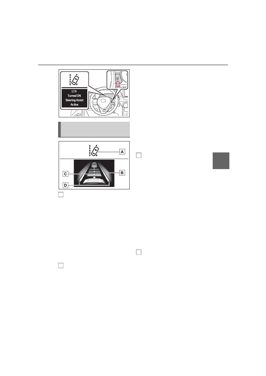
LTA indicator

The illumination condition of the 
indicator informs the driver of the 
system operation status.
Illuminated in white: LTA system is 
operating.
Illuminated in green: Steering 
wheel assistance of the steering 
assist function or lane centering 
function is operating.
Flashing in orange: Lane departure 
alert function is operating.

Operation display of steering 
wheel operation support

Displayed when the multi-informa-
tion display is switched to the driv-
ing support system information 
display.
Indicates that steering wheel assis-
tance of the steering assist function 

or lane centering function is operat-
ing.
Both outer sides of the lane are dis-
played: Indicates that steering 
wheel assist of the lane centering 
function is operating.
One outer side of the lane is dis-
played: Indicates that steering 
wheel assist of the steering assist 
function is operating.
Both outer sides of the lane are 
flashing: Alerts the driver that their 
input is necessary to stay in the 
center of the lane (lane centering 
function).

Follow-up cruising display

Displayed when the multi-informa-
tion display is switched to the driv-
ing support system information 
display.
Indicates that steering assist of the 
lane centering function is operating 
by monitoring the position of a pre-
ceding vehicle.
When the follow-up cruising display 
is displayed, if the preceding vehi-
cle moves, your vehicle may move 
in the same way. Always pay care-
ful attention to your surroundings 
and operate the steering wheel as 
necessary to correct the path of the 
vehicle and ensure safety.

Lane departure alert function 
display

Displayed when the multi-informa-
tion display is switched to the driv-
ing support system information 
display.

Indications on multi-infor-
mation display

A

B

C

D

242

4-5. Using the driving support systems

Inside of displayed lines is 
white

Indicates that the system is recog-
nizing white (yellow) lines or a 
course

*

. When the vehicle departs 

from its lane, the white line dis-
played on the side the vehicle 
departs from flashes orange.

Inside of displayed lines is 
black

Indicates that the system is not able 
to recognize white (yellow) lines or 
a course

*

 or is temporarily can-

celed.

*

: Boundary between asphalt and 

the side of the road, such as 
grass, soil, or a curb

Operation conditions of each 

function

Lane departure alert function

This function operates when all of 
the following conditions are met.

• LTA is turned on.

• Vehicle speed is approximately 32 

mph (50 km/h) or more.

*1

• System recognizes white (yellow) 

lane lines or a course

*2

. (When a 

white [yellow] line or course

*2

 is 

recognized on only one side, the 

system will operate only for the 

recognized side.)

• Width of traffic lane is approxi-

mately 9.8 ft. (3 m) or more.

• Turn signal lever is not operated. 

(Vehicles with BSM: Except when 

another vehicle is in the lane on 

the side where the turn signal was 

operated)

• Vehicle is not being driven around 

a sharp curve.

• No system malfunctions are 

detected. (

P.244)

*1

:The function operates even if the 

vehicle speed is less than 
approximately 32 mph (50 km/h) 
when the lane centering function 
is operating.

*2

:Boundary between asphalt and 

the side of the road, such as 
grass, soil, or a curb

Steering assist function

This function operates when all of 
the following conditions are met in 
addition to the operation conditions 
for the lane departure alert function.
• Setting for “Steering Assist” in the 

 screen of the multi-information 

display is set to “ON”. (

P.94)

• Vehicle is not accelerated or 

decelerated by a fixed amount or 

more.

• Steering wheel is not operated 

with a steering force level suitable 

for changing lanes.

• ABS, VSC, TRAC and PCS are 

not operating.

• TRAC or VSC is not turned off.

• Hands off steering wheel warning 

is not displayed. (

P.244)

Vehicle sway warning function

243

4-5. Using the driving support systems

4

Dr

iv

ing

This function operates when all of 
the following conditions are met.
• Setting for “Sway Warning” in the 

 screen of the multi-information 

display is set to “ON”. (

P.89)

• Vehicle speed is approximately 32 

mph (50 km/h) or more.

• Width of traffic lane is approxi-

mately 9.8 ft. (3 m) or more.

• No system malfunctions are 

detected. (

P.244)

Lane centering function

This function operates when all of 
the following conditions are met.
• LTA is turned on.

• Setting for “Steering Assist” and 

“Lane Center” in the 

 screen of 

the multi-information display is set 

to “ON”. (

P.89)

• This function recognizes white 

(yellow) lane lines or the position 

of a preceding vehicle (except 

when the preceding vehicle is 

small, such as a motorcycle).

• The dynamic radar cruise control 

with full-speed range is operating 

in vehicle-to-vehicle distance con-

trol mode.

• Width of traffic lane is approxi-

mately 10 to 13 ft. (3 to 4 m).

• Turn signal lever is not operated.

• Vehicle is not being driven around 

a sharp curve.

• No system malfunctions are 

detected. (

P.244)

• Vehicle does not accelerate or 

decelerate by a fixed amount or 

more.

• Steering wheel is not operated 

with a steering force level suitable 

for changing lanes.

• ABS, VSC, TRAC and PCS are 

not operating.

• TRAC or VSC is not turned off.

• Hands off steering wheel warning 

is not displayed. (

P.244)

• The vehicle is being driven in the 

center of a lane.

• Steering assist function is not 

operating.

Temporary cancelation of func-

tions

When operation conditions are no 

longer met, a function may be 

temporarily canceled. However, 

when the operation conditions are 

met again, operation of the func-

tion is automatically restored. 

(

P.242)

If the operation conditions 

(

P.242) are no longer met while 

the lane centering function is 

operating, the buzzer may sound 

to indicate that the function has 

been temporarily canceled.

Steering assist function/lane 

centering function

Depending on the vehicle speed, 

lane departure situation, road con-

ditions, etc., the driver may not 

feel the function is operating or 

the function may not operate at 

all.

The steering control of the func-

tion is overridden by the driver’s 

steering wheel operation.

Do not attempt to test the opera-

tion of the steering assist function.

Lane departure alert function

The warning buzzer may be diffi-

cult to hear due to external noise, 

audio playback, etc.

If the edge of the course

*

 is not 

clear or straight, the lane depar-

ture alert function may not oper-

ate.

Vehicles with BSM: It may not be 

possible for the system to deter-

mine if there is a danger of a colli-

sion with a vehicle in an adjacent 

lane.

Do not attempt to test the opera-

tion of the lane departure alert 

function.

*

: Boundary between asphalt and 

the side of the road, such as 
grass, soil, or a curb

244

4-5. Using the driving support systems

Hands off steering wheel warn-

ing

In the following situations, a warning 

message urging the driver to hold 

the steering wheel and the symbol 

shown in the illustration are dis-

played on the multi-information dis-

play to warn the driver. The warning 

stops when the system determines 

that the driver holds the steering 

wheel. Always keep your hands on 

the steering wheel when using this 

system, regardless of warnings.

When the system determines that 

the driver is driving without hold-

ing the steering wheel while the 

system is operating

If the driver continues to keep their 
hands off of the steering wheel, the 
buzzer sounds, the driver is warned 
and the function is temporarily can-
celed. This warning also operates in 
the same way when the driver con-
tinuously operates the steering 
wheel only a small amount.

When the system determines that 

the vehicle may deviate from the 

lane while driving around a curve 

while the lane centering function is 

operating.

Depending on the vehicle condition 
and road conditions, the warning 
may not operate. Also, if the system 
determines that the vehicle is driv-
ing around a curve, warnings will 
occur earlier than during straight-
lane driving.

When the system determines that 

the driver is driving without hold-

ing the steering wheel while the 

steering wheel assist of the steer-

ing assist function is operating.

If the driver continues to keep their 
hands off of the steering wheel and 
the steering wheel assist is operat-
ing, the buzzer sounds and the 
driver is warned. Each time the 
buzzer sounds, the continuing time 
of the buzzer becomes longer.

Vehicle sway warning function

When the system determines that 

the vehicle is swaying while the 

vehicle sway warning function is 

operating, a buzzer sounds and a 

warning message urging the driver 

to rest and the symbol shown in the 

illustration are simultaneously dis-

played on the multi-information dis-

play.

Depending on the vehicle and road 

conditions, the warning may not 

operate.

Warning message

If the following warning message is 

displayed on the multi-information 

display and the LTA indicator illumi-

nates in orange, follow the appropri-

ate troubleshooting procedure. Also, 

if a different warning message is 

displayed, follow the instructions 

displayed on the screen.

“LTA Malfunction Visit Your 

Dealer”

The system may not be operating 
properly. Have the vehicle inspected 
by your Toyota dealer.

“LTA Unavailable”

The system is temporarily canceled 

245

4-5. Using the driving support systems

4

Dr

iv

ing

due to a malfunction in a sensor 
other than the front camera. Turn 
the LTA system off, wait for a little 
while, and then turn the LTA system 
back on.

“LTA Unavailable at Current 

Speed”

The function cannot be used as the 
vehicle speed exceeds the LTA 
operation range. Drive slower.

Customization

Function settings can be changed. 

(

P.94)

*

: If equipped

RSA (Road Sign 

Assist)

*

The RSA system recognizes 
specific road signs using 
the front camera to provide 
information to the driver via 
the display.

If the system judges that the 
vehicle is being driven over 
the speed limit, performing 
prohibited actions, etc. 
according to the recog-
nized road signs, it notifies 
the driver through a visual 
notification and notification 
buzzer.

WARNING

Before using the RSA

Do not rely solely upon the RSA 

system. RSA is a system which 

supports the driver by providing 

information, but it is not a replace-

ment for a driver’s own vision and 

awareness. Drive safely by 

always paying careful attention to 

the traffic rules.

246

4-5. Using the driving support systems

When the front camera recog-
nizes a sign, the sign will be dis-
played on the multi-information 
display.

When the driving support sys-
tem information display is 
selected, a maximum of 3 
signs can be displayed. 
(

P.89)

When a tab other than the 
driving support system infor-
mation display is selected, the 
following types of road signs 
will be displayed. (

P.89)

• Speed limit sign
• Do Not Enter sign (when notifica-

tion is necessary)

If signs other than speed limit 
signs are recognized, they will 

be displayed in an overlapping 
stack under the current speed 
limit sign.

The following types of road 
signs, including electronic signs 
and blinking signs, are recog-
nized.

A non-official or a recently intro-
duced traffic sign may not be recog-
nized.

In the following situations, the 
RSA system will notify the 
driver.

When the vehicle speed 
exceeds the speed notifica-
tion threshold of the speed 
limit sign displayed, the sign 
display will be emphasized 
and a buzzer will sound.

When the RSA system recog-

Indication on the multi-
information display

Supported types of road 
signs

Speed limit

Do Not Enter

Stop

Yield

Notification function

247

4-5. Using the driving support systems

4

Dr

iv

ing

nizes a do not enter sign and 
determines that your vehicle 
has entered a no-entry area, 
the displayed sign will flash 
and a buzzer will sound.

Depending on the situation, a 
notification function may not 
operate properly.

Setting procedure

P.94

Automatic turn-off of RSA sign 

display

In the following situations, a dis-

played speed limit sign and/or do 

not enter sign will stop being dis-

played automatically:

No sign has been recognized for a 

certain distance.

The road changes due to a left or 

right turn, etc.

In the following situations, stop and 

yield signs will stop being displayed 

automatically:

The system determines that your 

vehicle has passed the sign.

The road changes due to a left or 

right turn, etc.

Conditions in which the func-

tion may not operate or detect 

correctly

In the following situations, RSA 

does not operate normally and may 

not recognize signs, display the 

incorrect sign, etc. However, this 

does not indicate a malfunction.

The front camera is misaligned 

due to a strong impact being 

applied to the sensor, etc.

Dirt, snow, stickers, etc. are on the 

windshield near the front camera.

In inclement weather such as 

heavy rain, fog, snow or sand 

storms.

Light from an oncoming vehicle, 

the sun, etc. enters the front cam-

era.

The sign is dirty, faded, tilted or 

bent.

The contrast of electronic sign is 

low.

All or part of the sign is hidden by 

the leaves of a tree, a pole, etc.

The sign is only visible to the front 

camera for a short amount of time.

The driving scene (turning, lane 

change, etc.) is judged incorrectly.

If a sign not appropriate for the 

currently traveled lane, but the 

sign exists directly after a freeway 

branches, or in an adjacent lane 

just before merging.

Stickers are attached to the rear 

of the preceding vehicle.

A sign resembling a system com-

patible sign is recognized.

Side road speed signs may be 

detected and displayed (if posi-

tioned in sight of the front camera) 

while the vehicle is traveling on 

the main road.

Roundabout exit road speed signs 

may be detected and displayed (if 

positioned in sight of the front 

camera) while traveling on a 

roundabout.

The front of the vehicle is raised or 

lowered due to the carried load.

The surrounding brightness is not 

sufficient or changes suddenly.

When a sign intended for trucks, 

etc. is recognized.

The speed information displayed 

on the meter and on the naviga-

tion system may be different due 

to the navigation system using 

map data.

Speed limit sign display

If the engine switch was last turned 

off while a speed limit sign was dis-

played on the multi-information dis-

play, the same sign displays again 

248

4-5. Using the driving support systems

when the engine switch is turned to 

ON.

If “RSA Malfunction Visit Your 

Dealer” is shown

The system may be malfunctioning. 

Have the vehicle inspected by your 

Toyota dealer.

Customization

Some functions can be customized. 

(

P.94)

Meter display

Multi-information display

Set speed

Dynamic radar cruise 

control with full-speed 

range

In vehicle-to-vehicle dis-
tance control mode, the 
vehicle automatically accel-
erates, decelerates and 
stops to match the speed 
changes of the preceding 
vehicle even if the accelera-
tor pedal is not depressed. 
In constant speed control 
mode, the vehicle runs at a 
fixed speed.

Use the dynamic radar 
cruise control with full-
speed range on freeways 
and highways.

Vehicle-to-vehicle distance 
control mode (

P.251)

Constant speed control 
mode (

P.256)

System Components

A

B

249

4-5. Using the driving support systems

4

Dr

iv

ing

Indicators

Operation switches

Vehicle-to-vehicle distance 
switch

“+RES” switch

Cruise control main switch

Cancel switch

“-SET” switch

WARNING

Before using dynamic radar 

cruise control with full-speed 

range

Driving safely is the sole 

responsibility of the driver. Do 

not rely solely on the system, 

and drive safely by always pay-

ing careful attention to your sur-

roundings.

C

A

B

C

D

E

The dynamic radar cruise con-

trol with full-speed range pro-

vides driving assistance to 

reduce the driver’s burden. 

However, there are limitations 

to the assistance provided.

Read the following conditions 
carefully. Do not overly rely on 
this system and always drive 
carefully.
• When the sensor may not be 

correctly detecting the vehicle 

ahead: 

P.257

• Conditions under which the 

vehicle-to-vehicle distance con-

trol mode may not function cor-

rectly: 

P.258

Set the speed appropriately 

depending on the speed limit, 

traffic flow, road conditions, 

weather conditions, etc. The 

driver is responsible for check-

ing the set speed.

Even when the system is func-

tioning normally, the condition 

of the preceding vehicle as 

detected by the system may dif-

fer from the condition observed 

by the driver. Therefore, the 

driver must always remain alert, 

assess the danger of each situ-

ation and drive safely. Relying 

solely on this system or assum-

ing the system ensures safety 

while driving can lead to an 

accident, resulting in death or 

serious injury.

Switch the dynamic radar cruise 

control with full-speed range 

setting to off, using the cruise 

control main switch when not in 

use.

250

4-5. Using the driving support systems

WARNING

Cautions regarding the driv-

ing assist systems

Observe the following precau-

tions, as there are limitations to 

the assistance provided by the 

system. Failure to do so may 

cause an accident resulting in 

death or serious injury.

Assisting the driver to measure 

following distance

The dynamic radar cruise control 
with full-speed range is only 
intended to help the driver in 
determining the following distance 
between the driver’s own vehicle 
and a designated vehicle traveling 
ahead. It is not a mechanism that 
allows careless or inattentive driv-
ing, and it is not a system that can 
assist the driver in low-visibility 
conditions.
It is still necessary for driver to 
pay close attention to the vehi-
cle’s surroundings.

Assisting the driver to judge 

proper following distance

The dynamic radar cruise control 
with full-speed range determines 
whether the following distance 
between the driver’s own vehicle 
and a designated vehicle traveling 
ahead is within a set range. It is 
not capable of making any other 
type of judgement. Therefore, it is 
absolutely necessary for the 
driver to remain vigilant and to 
determine whether or not there is 
a possibility of danger in any 
given situation.

Assisting the driver to operate 

the vehicle

The dynamic radar cruise control 
with full-speed range does not 
include functions which will pre-
vent or avoid collisions with vehi-
cles ahead of your vehicle. 
Therefore, if there is ever any 
possibility of danger, the driver 
must take immediate and direct 
control of the vehicle and act 
appropriately in order to ensure 
the safety of all involved.

Situations unsuitable for 

dynamic radar cruise control 

with full-speed range

Do not use dynamic radar cruise 

control with full-speed range in 

any of the following situations. 

Doing so may result in inappropri-

ate speed control and could 

cause an accident resulting in 

death or serious injury.

Roads where there are pedes-

trians, cyclists, etc.

In heavy traffic

On roads with sharp bends

On winding roads

On slippery roads, such as 

those covered with rain, ice or 

snow

On steep downhills, or where 

there are sudden changes 

between sharp up and down 

gradients

Vehicle speed may exceed the 

set speed when driving down a 

steep hill.

At entrances to freeways and 

highways

251

4-5. Using the driving support systems

4

Dr

iv

ing

This mode employs a radar to detect the presence of vehicles up to 
approximately 328 ft. (100 m) ahead, determines the current vehicle-
to-vehicle following distance, and operates to maintain a suitable fol-
lowing distance from the vehicle ahead. The desired vehicle-to-vehi-
cle distance can also be set by operating the vehicle-to-vehicle 
distance switch.

When driving on downhill slopes, the vehicle-to-vehicle distance may 
become shorter.

WARNING

When weather conditions are 

bad enough that they may pre-

vent the sensors from detecting 

correctly (fog, snow, sandstorm, 

heavy rain, etc.)

When there is rain, snow, etc. 

on the front surface of the radar 

or front camera

In traffic conditions that require 

frequent repeated acceleration 

and deceleration

When your vehicle is towing a 

trailer or during emergency tow-

ing

When an approach warning 

buzzer is heard often

Driving in vehicle-to-vehicle distance control mode

252

4-5. Using the driving support systems

Example of constant speed cruising
When there are no vehicles ahead

The vehicle travels at the speed set by the driver.

Example of deceleration cruising and follow-up cruising
When a preceding vehicle driving slower than the set speed 
appears

When a vehicle is detected running ahead of you, the system automatically 
decelerates your vehicle. When a greater reduction in vehicle speed is nec-
essary, the system applies the brakes (the stop lights will come on at this 
time). The system will respond to changes in the speed of the vehicle 
ahead in order to maintain the vehicle-to-vehicle distance set by the driver. 
Approach warning warns you when the system cannot decelerate suffi-
ciently to prevent your vehicle from closing in on the vehicle ahead.
When the vehicle ahead of you stops, your vehicle will also stop (vehicle is 
stopped by system control). After the vehicle ahead starts off, pressing the 
“+RES” switch or depressing the accelerator pedal (start-off operation) will 
resume follow-up cruising. If the start-off operation is not performed, system 
control continues to keep your vehicle stopped.
When the turn signal lever is operated and your vehicle moves to an over-
taking lane while driving at 50 mph (80 km/h) or more, the vehicle will accel-
erate to help to overtake a passing vehicle.
The system’s identification of what is an overtaking lane may be deter-
mined solely based on the location of the steering wheel in the vehicle (left 
side driver position versus right side driver position.) If the vehicle is driven 
to a region where the overtaking lane is on a different side from where the 
vehicle is normally driven, the vehicle may accelerate when the turn signal 
lever is operated in the opposite direction to the overtaking lane (e.g., if the 
driver normally operates the vehicle in a region where the overtaking lane is 
to the right but then drives to a region where the overtaking lane is to the 
left, the vehicle may accelerate when the right turn signal is activated).

Example of acceleration
When there are no longer any preceding vehicles driving slower 
than the set speed

The system accelerates until the set speed is reached. The system then 
returns to constant speed cruising.

1

Press the cruise control main 

switch to activate the cruise 
control.

Dynamic radar cruise control indi-

cator will come on and a message 

will be displayed on the multi-infor-

mation display. Press the switch 

A

B

C

Setting the vehicle speed 
(vehicle-to-vehicle dis-
tance control mode)

253

4-5. Using the driving support systems

4

Dr

iv

ing

again to deactivate the cruise con-

trol.
If the cruise control main switch is 

pressed and held for 1.5 seconds 

or more, the system turns on in 

constant speed control mode. 

(

P.256)

2

Accelerate or decelerate, 
with accelerator pedal opera-
tion, to the desired vehicle 
speed (at or above approxi-
mately 20 mph [30 km/h]) 
and press the “-SET” switch 
to set the speed.

Cruise control “SET” indicator will 

come on.
The vehicle speed at the moment 

the switch is released becomes the 

set speed.

To change the set speed, press 
the “+RES” or “-SET” switch 
until the desired set speed is 

displayed.

1

Increases the speed (Except 
when the vehicle has been 
stopped by system control in 
vehicle-to-vehicle distance 
control mode)

2

Decreases the speed

Fine adjustment: Press the switch.
Large adjustment: Press and hold 
the switch to change the speed, 
and release when the desired 
speed is reached.

In the vehicle-to-vehicle dis-
tance control mode, the set 
speed will be increased or 
decreased as follows:

For the U.S. mainland and 
Hawaii

Fine adjustment: By 1 mph (1.6 
km/h)

*1

 or 1 km/h (0.6 mph)

*2

 each 

time the switch is pressed
Large adjustment: Increases or 
decreases in 1 mph (1.6 km/h)

*1

 or 

1 km/h (0.6 mph)

*2

 increments for 

as long as the switch is held

Except for the U.S. mainland 
and Hawaii

Fine adjustment: By 1 mph (1.6 
km/h)

*1

 or 1 km/h (0.6 mph)

*2

 each 

time the switch is pressed

Adjusting the set speed

254

4-5. Using the driving support systems

Large adjustment: Increases or 
decreases in 5 mph (8 km/h)

*1

 or 5 

km/h (3.1 mph)

*2

 increments for as 

long as the switch is held

In the constant speed control 
mode (

P.256), the set speed 

will be increased or decreased 
as follows:

Fine adjustment: By 1 mph (1.6 
km/h)

*1

 or 1 km/h (0.6 mph)

*2

 each 

time the switch is pressed
Large adjustment: The speed will 
continue to change while the switch 
is held.

*1

:When the set speed is shown in 

“MPH”

*2

:When the set speed is shown in 

“km/h”

Pressing the switch changes the 
vehicle-to-vehicle distance as 
follows:

1

Long

2

Medium

3

Short

If a vehicle is running ahead of you, 
the preceding vehicle mark 

 will 

also be displayed.

Select a distance from the table 
below. Note that the distances 
shown correspond to a vehicle 
speed of 50 mph (80 km/h). 
Vehicle-to-vehicle distance 
increases/decreases in accor-
dance with vehicle speed. When 
the vehicle is stopped by system 
control, the vehicle stops at a 
certain vehicle-to-vehicle dis-
tance depending on the situa-
tion.

After the vehicle ahead of you 

Changing the vehicle-to-
vehicle distance (vehicle-
to-vehicle distance con-
trol mode)

Vehicle-to-vehicle dis-
tance settings (vehicle-to-
vehicle distance control 
mode)

Distance options

Vehicle-to-vehi-

cle distance

Long

Approximately 

160 ft. (50 m)

Medium

Approximately 

130 ft. (40 m)

Short

Approximately 

100 ft. (30 m)

Resuming follow-up 
cruising when the vehicle 
has been stopped by sys-
tem control (vehicle-to-
vehicle distance control 
mode)

A

255

4-5. Using the driving support systems

4

Dr

iv

ing

starts off, press the “+RES” 
switch.
Your vehicle will also resume 
follow-up cruising if the acceler-
ator pedal is depressed after the 
vehicle ahead of you starts off.

1

Pressing the cancel switch 
cancels the speed control.

The speed control is also canceled 
when the brake pedal is depressed. 
(When the vehicle has been 
stopped by system control, 
depressing the brake pedal does 
not cancel the setting.)

2

Pressing the “+RES” switch 
resumes the cruise control 
and returns vehicle speed to 
the set speed.

When your vehicle is too close 
to a vehicle ahead, and suffi-
cient automatic deceleration via 
the cruise control is not possi-
ble, the display will flash and the 
buzzer will sound to alert the 
driver. An example of this would 
be if another driver cuts in front 
of you while you are following a 
vehicle. Depress the brake 
pedal to ensure an appropriate 
vehicle-to-vehicle distance.

Warnings may not occur 
when

In the following instances, warn-
ings may not occur even when 
the vehicle-to-vehicle distance is 
small.

When the speed of the pre-
ceding vehicle matches or 
exceeds your vehicle speed

When the preceding vehicle is 
traveling at an extremely slow 
speed

Immediately after the cruise 
control speed was set

Canceling and resuming 
the speed control

Approach warning (vehi-
cle-to-vehicle distance 
control mode)

256

4-5. Using the driving support systems

When depressing the acceler-
ator pedal

When constant speed control 
mode is selected, your vehicle 
will maintain a set speed without 
controlling the vehicle-to-vehi-
cle distance. Select this mode 
only when vehicle-to-vehicle dis-
tance control mode does not 
function correctly due to a dirty 
radar, etc.

1

With the cruise control off, 
press and hold the cruise 
control main switch for 1.5 
seconds or more.

Immediately after the switch is 

pressed, the dynamic radar cruise 

control indicator will come on. After-

wards, it switches to the cruise con-

trol indicator.
Switching to constant speed control 

mode is only possible when operat-

ing the switch with the cruise con-

trol off.

2

Accelerate or decelerate, 
with accelerator pedal opera-
tion, to the desired vehicle 
speed (at or above approxi-
mately 20 mph [30 km/h]) 

and press the “-SET” switch 
to set the speed.

Cruise control “SET” indicator will 

come on.
The vehicle speed at the moment 

the switch is released becomes the 

set speed.
Adjusting the speed setting: 

P.253

Canceling and resuming the speed 

setting: 

P.255

Dynamic radar cruise control 

with full-speed range can be set 

when

The shift lever is in D.

The desired set speed can be set 

when the vehicle speed is approx-

imately 20 mph (30 km/h) or more. 

(However, when the vehicle speed 

is set while driving at below 

approximately 20 mph [30 km/h], 

the set speed will be set to 

approximately 20 mph [30 km/h].)

Accelerating after setting the 

vehicle speed

The vehicle can accelerate by oper-

ating the accelerator pedal. After 

accelerating, the set speed 

resumes. However, during vehicle- 

to-vehicle distance control mode, 

the vehicle speed may decrease 

below the set speed in order to 

maintain the distance to the preced-

ing vehicle.

Selecting constant speed 
control mode


Content      ..     13      14      15      16     ..