Toyota Corolla (2022 year). Manual in english - page 33
 

  Index      Toyota     Toyota Corolla (2022 year). Manual in english


Search            copyright infringement  


Content      ..     31      32      33      34     ..


Toyota Corolla (2022 year). Manual in english - page 33


525

8-2. Steps to take in an emergency

8

Whe

n tr

ouble

 ar

ises

(

P.558): Proceed to step 

23

.

22

Turn the compressor switch 

on to inflate the tire until the 
specified air pressure is 
reached. Drive for about 3 
miles (5 km) and then per-
form step 

20

.

23

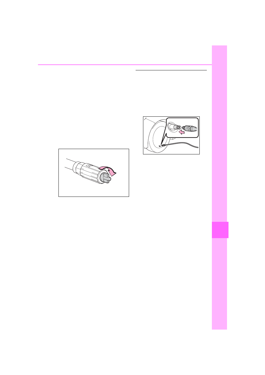
Attach the air release cap to 

the end of the hose.

If the air release cap is not 

attached, the sealant may leak and 

the vehicle may get dirty.

24

Store the bottle in the trunk 

while it is connected to the 
compressor.

25

Taking precautions to avoid 

sudden braking, sudden 
acceleration and sharp turns, 
drive carefully at under 50 
mph (80 km/h) to the nearest 
Toyota dealer that is less 
than 62 miles (100 km) away 
for tire repair or replacement.

When having the tire repaired or 

replaced, make sure to tell the Toy-

ota dealer that the sealant is 

injected.

If the tire is inflated to more 

than the specified air pressure

1

Disconnect the hose from the 

valve.

2

Install the air release cap to the 

end of the hose and push the 

protrusion on the air release cap 

into the tire valve to let some air 

out.

3

Disconnect the hose from the 

valve, remove the air release cap 

from the hose and then recon-

nect the hose.

4

Turn the compressor switch on 

and wait for several seconds, 

and then turn it off. Check that 

the air pressure indicator shows 

the specified air pressure. 

(

P.558)

If the air pressure is under the des-

ignated pressure, turn the compres-

sor switch on again and repeat the 

inflation procedure until the speci-

fied air pressure is reached.

The valve of a tire that has been 

repaired (vehicles without a tire 

pressure warning system)

After a tire is repaired with the emer-

gency tire puncture repair kit, the 

valve should be replaced.

After a tire is repaired with the 

emergency tire puncture repair 

kit (vehicles with a tire pressure 

warning system)

The tire pressure warning valve 

and transmitter should be 

replaced.

Even if the tire inflation pressure is 

at the recommended level, the tire 

pressure warning light may come 

526

8-2. Steps to take in an emergency

on/flash.

WARNING

Do not drive the vehicle with 

a flat tire

Do not continue driving with a flat 

tire.

Driving even a short distance with 

a flat tire can damage the tire and 

the wheel beyond repair.
Driving with a flat tire may cause a 

circumferential groove on the side 

wall. In such a case, the tire may 

explode when using a repair kit.

When fixing the flat tire

Stop your vehicle in a safe and 

flat area.

Do not touch the wheels or the 

area around the brakes immedi-

ately after the vehicle has been 

driven.

After the vehicle has been 

driven, the wheels and the area 

around the brakes may be 

extremely hot. Touching these 

areas with hands, feet or other 

body parts may result in burns.

Connect the valve and hose 

securely with the tire installed 

on the vehicle. If the hose is not 

properly connected to the valve, 

air leakage may occur as seal-

ant may be sprayed out.

If the hose comes off the valve 

while inflating the tire, there is a 

risk that the hose will move 

abruptly due to air pressure.

After inflation of the tire has 

completed, the sealant may 

splatter when the hose is dis-

connected or some air is let out 

of the tire.

Follow the operation procedure 

to repair the tire. If the proce-

dures not followed, the sealant 

may spray out.

Keep back from the tire while it 

is being repaired, as there is a 

chance of it bursting while the 

repair operation is being per-

formed. If you notice any cracks 

or deformation of the tire, turn 

off the compressor switch and 

stop the repair operation imme-

diately.

The repair kit may overheat if 

operated for a long period of 

time. Do not operate the repair 

kit continuously for more than 

40 minutes.

Parts of the repair kit become 

hot during operation. Be careful 

handling the repair kit during 

and after operation. Do not 

touch the metal part connecting 

the bottle and the compressor. It 

will be extremely hot.

Do not attach the vehicle speed 

warning sticker to an area other 

than the one indicated. If the 

sticker is attached to an area 

where an SRS airbag is located, 

such as the pad of the steering 

wheel, it may prevent the SRS 

airbag from operating properly.

Driving to spread the liquid 

sealant evenly

Observe the following precautions 

to reduce the risk of accidents.

Failing to do so may result in a 

loss of vehicle control and cause 

death or serious injury.

Drive the vehicle carefully at a 

low speed. Be especially careful 

when turning and cornering.

If the vehicle does not drive 

straight or you feel a pull 

through the steering wheel, stop 

the vehicle and check the fol-

lowing.

• Tire condition. The tire may 

have separated from the wheel.

527

8-2. Steps to take in an emergency

8

W

he

tro

ub

le

 ar

is

es

WARNING

• Tire inflation pressure. If the tire 

inflation pressure is 19 psi (130 
kPa, 1.3 kgf/cm

2

 or bar) or less, 

the tire may be severely dam-

aged.

NOTICE

When performing an emer-

gency repair

A tire should only be repaired 

with the emergency tire punc-

ture repair kit if the damage is 

caused by a sharp object such 

as nail or screw passing through 

the tire tread.

Do not remove the sharp object 

from the tire. Removing the 

object may widen the opening 

and disenable emergency repair 

with the repair kit.

The repair kit is not waterproof. 

Make sure that the repair kit is 

not exposed to water, such as 

when it is being used in the rain.

Do not put the repair kit directly 

onto dusty ground such as sand 

at the side of the road. If the 

repair kit vacuums up dust etc., 

a malfunction may occur.

Precautions for the emer-

gency tire puncture repair kit

The repair kit power source 

should be 12 V DC suitable for 

vehicle use. Do not connect the 

repair kit to any other source.

If fuel splatters on the repair kit, 

the repair kit may deteriorate. 

Take care not to allow fuel to 

contact it.

Place the repair kit in a storage 

to prevent it from being exposed 

to dirt or water.

Store the repair kit in the trunk 

out of reach of children.

Do not disassemble or modify 

the repair kit. Do not subject 

parts such as the air pressure 

indicator to impacts. This may 

cause a malfunction.

To avoid damage to the tire 

pressure warning valves and 

transmitters (vehicles with a 

tire pressure warning system)

When a tire is repaired with liquid 

sealants, the tire pressure warn-

ing valve and transmitter may not 

operate properly. If a liquid seal-

ant is used, contact your Toyota 

dealer or other qualified service 

shop as soon as possible. After 

use of liquid sealant, make sure to 

replace the tire pressure warning 

valve and transmitter when repair-

ing or replacing the tire. (

P.473)

528

8-2. Steps to take in an emergency

Stop the vehicle in a safe 
place on a hard, flat surface.

Set the parking brake.

Shift the shift lever to P (con-
tinuously variable transmis-
sion) or R (manual 
transmission).

Stop the engine.

Turn on the emergency flash-
ers.

If you have a flat tire 

(vehicles with a spare 

tire)

Your vehicle is equipped 
with a spare tire. The flat tire 
can be replaced with the 
spare tire.

For details about tires: 

P.470

WARNING

If you have a flat tire

Do not continue driving with a flat 

tire. Driving even a short distance 

with a flat tire can damage the tire 

and the wheel beyond repair, 

which could result in an accident.

Before jacking up the 
vehicle

529

8-2. Steps to take in an emergency

8

Whe

n tr

ouble

 ar

ises

Type A

Jack handle
Jack
Towing eyelet
Spare tire
Wheel nut wrench

Location of the spare tire, jack and tools

530

8-2. Steps to take in an emergency

Type B

Jack
Wheel nut wrench
Spare tire
Jack handle

WARNING

Using the tire jack

Observe the following precau-

tions. Improper use of the tire jack 

may cause the vehicle to sud-

denly fall off the jack, leading to 

death or serious injury.

Do not use the tire jack for any 

purpose other than replacing 

tires or installing and removing 

tire chains.

Only use the tire jack that 

comes with this vehicle for 

replacing a flat tire. Do not use it 

on other vehicles, and do not 

use other tire jacks for replacing 

tires on this vehicle.

Put the jack properly in its jack 

point.

Do not put any part of your body 

under the vehicle while it is sup-

ported by the jack.

Do not start the engine or drive 

the vehicle while the vehicle is 

supported by the jack.

Do not raise the vehicle while 

someone is inside.

531

8-2. Steps to take in an emergency

8

W

he

tro

ub

le

 ar

is

es

1

Remove the deck mat.

2

Take out the jack.

Type A

Type B

For tightening
For loosening

1

Remove the deck mat. 
(

P.531)

2

Remove the tool tray.

Type A

Type B

WARNING

When raising the vehicle, do not 

put an object on or under the 

jack.

Do not raise the vehicle to a 

height greater than that required 

to replace the tire.

Use a jack stand if it is neces-

sary to get under the vehicle.

When lowering the vehicle, 

make sure that there is no-one 

near the vehicle. If there are 

people nearby, warn them 

vocally before lowering.

Taking out the jack

Taking out the spare tire

532

8-2. Steps to take in an emergency

3

Loosen the center fastener 

that secures the spare tire.

1

Chock the tires.

2

Vehicles with a steel wheel: 
Remove the wheel ornament 
(if equipped) using the 
wrench.

Insert the wrench into the notch 


on the wheel cap.

To protect the wheel ornament, 

place a rag between the wrench 

and the wheel ornament.

3

Slightly loosen the wheel 
nuts (one turn).

4

Turn the tire jack portion   
by hand until the center of the 
recessed portion of the jack 

WARNING

When storing the spare tire

Be careful not to catch fingers or 

other body parts between the 

spare tire and the body of the 

vehicle.

Replacing a flat tire

Flat tire

Wheel chock 

positions

Front left-hand 
side

Behind the rear 
right-hand side 
tire

Front right-hand 
side

Behind the rear 
left-hand side tire

Rear left-hand 
side

In front of the 
front right-hand 
side tire

Rear right-hand 
side

In front of the 
front left-hand 
side tire

Flat tire

Wheel chock 

positions

533

8-2. Steps to take in an emergency

8

W

he

tro

ub

le

 ar

is

es

is in contact with the center of 
the jack point.

5

Assemble the jack handle 
extension.

Type A

Type B

6

Raise the vehicle until the tire 
is slightly raised off the 
ground.

7

Remove all the wheel nuts 
and the tire.

When resting the tire on the 

ground, place the tire so that the 

wheel design faces up to avoid 

scratching the wheel surface.

WARNING

Replacing a flat tire

Do not touch the disc wheels or 

the area around the brakes 

immediately after the vehicle 

has been driven. After the vehi-

cle has been driven the disc 

wheels and the area around the 

brakes will be extremely hot. 

Touching these areas with 

hands, feet or other body parts 

while changing a tire, etc. may 

result in burns.

534

8-2. Steps to take in an emergency

1

Remove any dirt or foreign 
matter from the wheel con-
tact surface.

If foreign matter is on the wheel 

contact surface, the wheel nuts 

may loosen while the vehicle is in 

motion, causing the tire to come off.

2

Install the tire and loosely 
tighten each wheel nut by 
hand by approximately the 
same amount.

When replacing a steel wheel with 

a steel wheel (including a compact 

spare tire), tighten the wheel nuts 
until the tapered portion 

 comes 

into loose contact with the disc 
wheel seat 

.

When replacing an aluminum wheel 

with a steel wheel (including a com-

pact spare tire), tighten the wheel 
nuts until the tapered portion 


comes into loose contact with the 

WARNING

Failure to follow these precau-

tions could cause the wheel 

nuts to loosen and the tire to fall 

off, resulting in death or serious 

injury.

• Have the wheel nuts tightened 

with a torque wrench to 76 ft•lbf 

(103 N•m, 10.5 kgf•m) as soon 

as possible after changing 

wheels.

• Do not attach a heavily dam-

aged wheel ornament, as it may 

fly off the wheel while the vehi-

cle is moving.

• When installing a tire, only use 

wheel nuts that have been spe-

cifically designed for that wheel.

• If there are any cracks or defor-

mations in the bolt screws, nut 

threads or bolt holes of the 

wheel, have the vehicle 

inspected by your Toyota 

dealer.

• When installing the wheel nuts, 

be sure to install them with the 

tapered ends facing inward.

Installing the spare tire

535

8-2. Steps to take in an emergency

8

Whe

n tr

ouble

 ar

ises

disc wheel seat 

.

3

Lower the vehicle.

4

Firmly tighten each wheel nut 
two or three times in the 
order shown in the illustra-
tion.

Tightening torque:

76 ft•lbf (103 N•m, 10.5 kgf•m)

5

Stow the flat tire, tire jack and 
all tools.

The compact spare tire

The compact spare tire is identi-

fied by the label “TEMPORARY 

USE ONLY” on the tire sidewall. 

Use the compact spare tire tempo-

rarily, and only in an emergency.

Make sure to check the tire infla-

tion pressure of the compact 

spare tire. (

P.558)

When the compact spare tire is 

equipped

The vehicle becomes lower when 

driving with the compact spare tire 

compared to when driving with stan-

dard tires.

After completing the tire 

change (vehicles with a tire 

pressure warning system)

The tire pressure warning system 

must be reset. (

P.474)

When using the compact spare 

tire (vehicles with a tire pres-

sure warning system)

As the compact spare tire is not 

equipped with a tire pressure warn-

ing valve and transmitter, low infla-

tion pressure of the spare tire will 

not be indicated by the tire pressure 

warning system. Also, if you replace 

the compact spare tire after the tire 

pressure warning light comes on, 

the light remains on.

If you have a flat front tire on a 

road covered with snow or ice

Install the compact spare tire on one 

of the rear wheels of the vehicle. 

Perform the following steps and fit 

tire chains to the front tires:

1

Replace a rear tire with the com-

pact spare tire.

2

Replace the flat front tire with the 

tire removed from the rear of the 

vehicle.

3

Fit tire chains to the front tires.

When reinstalling the wheel 

ornament (steel wheels except 

compact spare tire)

Align the cutout of the wheel orna-

ment with the valve stem as shown 

in the illustration.

536

8-2. Steps to take in an emergency

WARNING

When using the compact 

spare tire

Remember that the compact 

spare tire provided is specifi-

cally designed for use with your 

vehicle. Do not use your com-

pact spare tire on another vehi-

cle.

Do not use more than one com-

pact spare tires simultaneously.

Replace the compact spare tire 

with a standard tire as soon as 

possible.

Avoid sudden acceleration, 

abrupt steering, sudden brak-

ing and shifting operations that 

cause sudden engine braking.

When the compact spare tire 

is attached

The vehicle speed may not be 

correctly detected, and the follow-

ing systems may not operate cor-

rectly:

• ABS & Brake assist

• VSC

• TRAC

• Automatic High Beam

• AFS (Adaptive Front-lighting 

System) (if equipped)

• Dynamic radar cruise control 

with full-speed range (if 

equipped)

• Dynamic radar cruise control (if 

equipped)

• EPS

• PCS (Pre-Collision System)

• LDA (Lane Departure Alert with 

steering control) (if equipped)

• LTA (Lane Tracing Assist) (if 

equipped)

• Tire pressure warning system (if 

equipped)

• BSM (Blind Spot Monitor) (if 

equipped)

• RCTA (Rear Cross Traffic Alert) 

function (if equipped)

• Rear view monitor system

• Navigation system (if equipped)

Speed limit when using the 

compact spare tire

Do not drive at speeds in excess 

of 50 mph (80 km/h) when a com-

pact spare tire is installed on the 

vehicle.

The compact spare tire is not 

designed for driving at high 

speeds. Failure to observe this 

precaution may lead to an acci-

dent causing death or serious 

injury.

After using the tools and jack

Before driving, make sure all the 

tools and jack are securely in 

place in their storage location to 

reduce the possibility of personal 

injury during a collision or sudden 

braking.

537

8-2. Steps to take in an emergency

8

W

he

tro

ub

le

 ar

is

es

One of the following may be the 
cause of the problem:

There may not be sufficient 
fuel in the vehicle’s tank. 
Refuel the vehicle.

The engine may be flooded. 
Try to restart the engine again 
following correct starting pro-
cedures. (

P.159, 160)

There may be a malfunction 
in the engine immobilizer sys-
tem. (

P.80)

One of the following may be the 
cause of the problem:

The battery may be dis-
charged. (

P.541)

NOTICE

Be careful when driving over 

bumps with the compact 

spare tire installed on the 

vehicle.

The vehicle becomes lower when 

driving with the compact spare tire 

compared to when driving with 

standard tires. Be careful when 

driving over uneven road sur-

faces.

Driving with tire chains and 

the compact spare tire

Do not fit tire chains to the com-

pact spare tire. Tire chains may 

damage the vehicle body and 

adversely affect driving perfor-

mance.

When replacing the tires 

(vehicles with a tire pressure 

warning system)

When removing or fitting the 

wheels, tires or the tire pressure 

warning valve and transmitter, 

contact your Toyota dealer as the 

tire pressure warning valve and 

transmitter may be damaged if not 

handled correctly.

To avoid damage to the tire 

pressure warning valves and 

transmitters (vehicles with a 

tire pressure warning system)

When a tire is repaired with liquid 

sealants, the tire pressure warn-

ing valve and transmitter may not 

operate properly. If a liquid seal-

ant is used, contact your Toyota 

dealer or other qualified service 

shop as soon as possible. Make 

sure to replace the tire pressure 

warning valve and transmitter 

when replacing the tire.

If the engine will not 

start

If the engine will not start 
even though correct starting 
procedures are being fol-
lowed (

P.159, 160), con-

sider each of the following 
points:

The engine will not start 
even though the starter 
motor operates normally.

The starter motor turns 
over slowly, the interior 
lights and headlights are 
dim, or the horn does not 
sound or sounds at a low 
volume.

538

8-2. Steps to take in an emergency

The battery terminal connec-
tions may be loose or cor-
roded. (

P.467)

The engine starting system may 
be malfunctioning due to an 
electrical problem such as elec-
tronic key battery depletion or a 
blown fuse. However, an interim 
measure is available to start the 
engine. (

P.538)

One of the following may be the 
cause of the problem:

The battery may be dis-
charged. (

P.541)

One or both of the battery ter-
minals may be disconnected. 
(

P.467)

There may be a malfunction 
in the steering lock system.

Contact your Toyota dealer if the 
problem cannot be repaired, or if 
repair procedures are unknown.

When the engine does not start, 
the following steps can be used 
as an interim measure to start 
the engine if the engine switch is 
functioning normally.
Do not use this starting proce-
dure except in case of emer-
gency.

1

Set the parking brake. 
(

P.176, 177)

2

Check that the shift lever is in 
P (continuously variable 
transmission) or N (manual 
transmission).

3

Turn the engine switch to 
ACC.

4

Press and hold the engine 
switch for about 15 seconds 
while depressing the brake 
pedal (continuously variable 
transmission) or clutch pedal 
(manual transmission) firmly.

Even if the engine can be started 
using the above steps, the system 
may be malfunctioning. Have the 
vehicle inspected by your Toyota 
dealer.

The starter motor does 
not turn over (vehicles 
with a smart key system)

The starter motor does 
not turn over, the interior 
lights and headlights do 
not turn on, or the horn 
does not sound.

Emergency start function 
(vehicles with a smart key 
system)

539

8-2. Steps to take in an emergency

8

W

he

tro

ub

le

 ar

is

es

When the electronic key does 

not work properly

Make sure that the smart key sys-

tem has not been deactivated in 

the customization setting. If it is 

off, turn the function on. (Custom-

izable features: 

P.574)

Check if battery-saving mode is 

set. If it is set, cancel the function. 

(

P.125)

Use the mechanical key 
(

P.112) in order to perform the 

If you lose your keys

New genuine keys can be 
made by your Toyota dealer 
using the other key (vehi-
cles without a smart key 
system) or mechanical key 
(vehicles with a smart key 
system) and the key number 
stamped on your key num-
ber plate.

Keep the plate in a safe 
place such as your wallet, 
not in the vehicle.

NOTICE

When an electronic key is lost 

(vehicles with a smart key 

system)

If the electronic key remains lost, 

the risk of vehicle theft increases 

significantly. Visit your Toyota 

dealer immediately with all 

remaining electronic keys that 

were provided with your vehicle.

If the electronic key 

does not operate prop-

erly (vehicles with a 

smart key system)

If communication between 
the electronic key and vehi-
cle is interrupted (

P.125) 

or the electronic key cannot 
be used because the battery 
is depleted, the smart key 
system and wireless remote 
control cannot be used. In 
such cases, the doors can 
be opened and the engine 
can be started by following 
the procedure below.

NOTICE

In case of a smart key system 

malfunction or other 

key-related problems

Take your vehicle with all the elec-

tronic keys provided with your 

vehicle to your Toyota dealer.

Locking and unlocking 
the doors

540

8-2. Steps to take in an emergency

following operations:

1

Locks all the doors

2

Unlocks all the doors

Turning the key unlocks the driver’s 
door. Turning the key again unlocks 
the other doors.

Key linked functions

1

Closes the windows and moon 
roof

*1

 (turn and hold)

*2

2

Opens the windows and moon 
roof

*1

 (turn and hold)

*2

*1

:If equipped

*2

:This setting must be customized 

at your Toyota dealer.

1

Vehicles with a continuously 
variable transmission: 
Ensure that the shift lever is 
in P and depress the brake 
pedal.
Vehicles with a manual trans-
mission: Shift the shift lever 
to N and depress the clutch 
pedal.

2

Touch the Toyota emblem 
side of the electronic key to 
the engine switch.

When the electronic key is 

detected, a buzzer sounds and the 

engine switch will turn to ON.
When the smart key system is 

deactivated in customization set-

ting, the engine switch will turn to 

WARNING

When using the mechanical 

key and operating the power 

windows or moon roof (if 

equipped)

Operate the power window or 

moon roof after checking to make 

sure that there is no possibility of 

any passenger having any of their 

body parts caught in the window 

or moon roof.

Also, do not allow children to 

operate the mechanical key. It is 

possible for children and other 

passengers to get caught in the 

power window or moon roof.

Starting the engine


Content      ..     31      32      33      34     ..