Toyota Corolla (2022 year). Manual in english - page 16
 

  Index      Toyota     Toyota Corolla (2022 year). Manual in english


Search            copyright infringement  


Content      ..     14      15      16      17     ..


Toyota Corolla (2022 year). Manual in english - page 16


248

4-5. Using the driving support systems

*

: If equipped

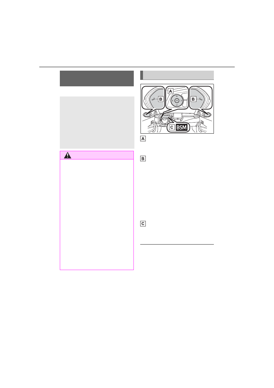
Meter control switches

Turning the Blind Spot Monitor 
on/off.

Outside rear view mirror indi-
cators

When a vehicle is detected in a 
blind spot of the outside rear view 
mirrors or approaching rapidly from 
behind into a blind spot, the outside 
rear view mirror indicator on the 
detected side will illuminate. If the 
turn signal lever is operated toward 
the detected side, the outside rear 
view mirror indicator flashes.

BSM indicator

Illuminates when the Blind Spot 
Monitor is enabled

Outside rear view mirror indica-

tor visibility

In strong sunlight, the outside rear 

view mirror indicator may be difficult 

to see.

When “Blind Spot Monitor 

Unavailable” is shown on the 

multi-information display

Ice, snow, mud, etc., may be 

attached to the rear bumper around 

the sensors. (

P.250) The system 

should return to normal operation 

after removing the ice, snow, mud, 

etc. from the rear bumper. Addition-

ally, the sensors may not operate 

BSM (Blind Spot Moni-

tor)

*

The Blind Spot Monitor is a 
system that uses rear side 
radar sensors installed on 
the inner side of the rear 
bumper on the left and right 
side to assist the driver in 
confirming safety when 
changing lanes.

WARNING

Cautions regarding the use of 

the system

The driver is solely responsible for 

safe driving. Always drive safely, 

taking care to observe your sur-

roundings.
The Blind Spot Monitor is a sup-

plementary function which alerts 

the driver that a vehicle is in a 

blind spot of the outside rear view 

mirrors or is approaching rapidly 

from behind into a blind spot. Do 

not overly rely on the Blind Spot 

Monitor. As the function cannot 

judge if it is safe to change lanes, 

over reliance could lead to an 

accident resulting in death or seri-

ous injury.
As the system may not function 

correctly under certain condi-

tions, the driver’s own visual con-

firmation of safety is necessary.

System components

249

4-5. Using the driving support systems

4

Dr

iv

ing

normally when driving in extremely 

hot or cold environments.

When “Blind Spot Monitor Mal-

function Visit Your Dealer” is 

shown on the multi-information 

display

There may be a sensor malfunction 

of misaligned. Have the vehicle 

inspected by your Toyota dealer.

Customization

Some functions can be customized. 

(

P.574)

Certification

Except for vehicles sold in Canada

For vehicles sold in Canada

250

4-5. Using the driving support systems

Use the meter control switches 
to turn on/off the function.

1

Press 

 or 

 to select 

.

2

Press 

 or 

 to select 


and then press 

.

WARNING

To ensure the system can 

operate properly

Blind Spot Monitor sensors are 

installed behind the left and right 

sides of the rear bumper respec-

tively. Observe the following to 

ensure the Blind Spot Monitor can 

operate correctly.

Keep the sensors and the sur-

rounding areas on the rear 

bumper clean at all times.

If a sensor or its surrounding area 
on the rear bumper is dirty or cov-
ered with snow, the Blind Spot 
Monitor may not operate and a 
warning message (

P.248) will 

be displayed. In this situation, 
clear off the dirt or snow and drive 
the vehicle with the operation con-
ditions of the BSM function 
(

P.252) satisfied for approxi-

mately 10 minutes. If the warning 
message does not disappear, 
have the vehicle inspected by 
your Toyota dealer.

Do not attach accessories, 

stickers (including transparent 

stickers), aluminum tape, etc. to 

a sensor or its surrounding area 

on the rear bumper.

Do not subject a sensor or its 

surrounding area on the rear 

bumper to a strong impact.

If a sensor is moved even 

slightly off position, the system 

may malfunction and vehicles 

may not be detected correctly.

In the following situations, have 

your vehicle inspected by your 

Toyota dealer.

• A sensor or its surrounding area 

is subject to a strong impact.

• If the surrounding area of a sen-

sor is scratched or dented, or 

part of them has become dis-

connected.

Do not disassemble the sensor.

Do not modify the sensor or sur-

rounding area on the rear 

bumper.

If a sensor or the rear bumper 

needs to be removed/installed 

or replaced, contact your Toyota 

dealer.

Do not paint the rear bumper 

any color other than an official 

Toyota color.

Turning the Blind Spot 
Monitor on/off

251

4-5. Using the driving support systems

4

Dr

iv

ing

Vehicles that can be detected by the Blind Spot Monitor

The Blind Spot Monitor uses rear side radar sensors to detect the fol-
lowing vehicles traveling in adjacent lanes and advises the driver of 
the presence of such vehicles via the indicators on the outside rear 
view mirrors.

Vehicles that are traveling in areas that are not visible using the 
outside rear view mirrors (the blind spots)
Vehicles that are approaching rapidly from behind in areas that 
are not visible using the outside rear view mirrors (the blind spots)

The Blind Spot Monitor detection areas

The areas that vehicles can be detected in are outlined below.

The range of each detection area is:

Approximately 1.6 ft. (0.5 m) to 11.5 ft. (3.5 m) from either side of 
the vehicle

*1

Approximately 3.3 ft. (1 m) forward of the rear bumper
Approximately 9.8 ft. (3 m) from the rear bumper
Approximately 9.8 ft. (3 m) to 197 ft. (60 m) from the rear 
bumper

*2

Blind Spot Monitor operation

252

4-5. Using the driving support systems

*1

:The area between the side of the vehicle and 1.6 ft. (0.5 m) from the side 

of the vehicle cannot be detected.

*2

:The greater the difference in speed between your vehicle and the 

detected vehicle is, the farther away the vehicle will be detected, causing 
the outside rear view mirror indicator to illuminate or flash.

The Blind Spot Monitor is oper-

ational when

The Blind Spot Monitor is opera-

tional when all of the following con-

ditions are met:

The Blind Spot Monitor is on.

The shift lever is in a position 

other than R.

The vehicle speed is greater than 

approximately 10 mph (16 km/h).

The Blind Spot Monitor will 

detect a vehicle when

The Blind Spot Monitor will detect a 

vehicle present in the detection area 

in the following situations:

A vehicle in an adjacent lane over-

takes your vehicle.

You overtake a vehicle in adjacent 

lane slowly.

Another vehicle enters the detec-

tion area when it changes lanes.

Conditions under which the 

system will not detect a vehicle

The Blind Spot Monitor is not 

designed to detect the following 

types of vehicles and/or objects:

Small motorcycles, bicycles, 
pedestrians, etc.

*

Vehicles traveling in the opposite 

direction

Guardrails, walls, signs, parked 

vehicles and similar stationary 
objects

*

Following vehicles that are in the 
same lane

*

Vehicles traveling 2 lanes away 
from your vehicle

*

Vehicles which are being over-

taken rapidly by your vehicle

*

*

: Depending on the conditions, 

detection of a vehicle and/or 
object may occur.

Conditions under which the 

system may not function cor-

rectly

The Blind Spot Monitor may not 

detect vehicles correctly in the fol-

lowing situations:

• When the sensor is misaligned 

due to a strong impact to the sen-

sor or its surrounding area

• When mud, snow, ice, a sticker, 

etc. is covering the sensor or sur-

rounding area on the rear bumper

• When driving on a road surface 

that is wet with standing water 

during bad weather, such as 

heavy rain, snow, or fog

• When multiple vehicles are 

approaching with only a small gap 

between each vehicle

• When the distance between your 

vehicle and a following vehicle is 

short

• When there is a significant differ-

ence in speed between your vehi-

cle and the vehicle that enters the 

detection area

• When the difference in speed 

between your vehicle and another 

vehicle is changing

• When a vehicle enters a detection 

area traveling at about the same 

speed as your vehicle

• As your vehicle starts from a stop, 

a vehicle remains in the detection 

area

• When driving up and down con-

secutive steep inclines, such as 

hills, dips in the road, etc.

• When driving on roads with sharp 

bends, consecutive curves, or 

uneven surfaces

253

4-5. Using the driving support systems

4

Dr

iv

ing

• When vehicle lanes are wide, or 

when driving on the edge of a 

lane, and the vehicle in an adja-

cent lane is far away from your 

vehicle

• When an accessory (such as a 

bicycle carrier) is installed to the 

rear of the vehicle

• When there is a significant differ-

ence in height between your vehi-

cle and the vehicle that enters the 

detection area

• Immediately after the Blind Spot 

Monitor is turned on

Instances of the Blind Spot Moni-

tor unnecessarily detecting a vehi-

cle and/or object may increase in 

the following situations:

• When the sensor is misaligned 

due to a strong impact to the sen-

sor or its surrounding area

• When the distance between your 

vehicle and a guardrail, wall, etc. 

that enters the detection area is 

short

• When driving up and down con-

secutive steep inclines, such as 

hills, dips in the road, etc.

• When vehicle lanes are narrow, or 

when driving on the edge of a 

lane, and a vehicle traveling in a 

lane other than the adjacent lanes 

enters the detection area

• When driving on roads with sharp 

bends, consecutive curves, or 

uneven surfaces

• When the tires are slipping or 

spinning

• When the distance between your 

vehicle and a following vehicle is 

short

• When an accessory (such as a 

bicycle carrier) is installed to the 

rear of the vehicle

*

: If equipped

RCTA (Rear Cross Traf-

fic Alert) function

*

The RCTA function uses the 
BSM rear side radar sensors 
installed behind the rear 
bumper. This function is 
intended to assist the driver 
in checking areas that are 
not easily visible when 
backing up.

WARNING

Cautions regarding the use of 

the system

There is a limit to the degree of 

recognition accuracy and control 

performance that this system can 

provide, do not overly rely on this 

system. The driver is always 

responsible for paying attention to 

the vehicle’s surroundings and 

driving safely. (

P.248)

To ensure the system can 

operate properly

P.250

System components

254

4-5. Using the driving support systems

Meter control switches

Turning the RCTA function on/off.
When the RCTA function is dis-
abled, the RCTA OFF indicator illu-
minates.

Outside rear view mirror indi-
cators

When a vehicle approaching from 
the right or left at the rear of the 
vehicle is detected, both outside 
rear view mirror indicators will flash.

Audio system display

If a vehicle approaching from the 
right or left at the rear of the vehicle 
is detected, the RCTA icon 
(

P.255) for the detected side will 

be displayed on the audio system 
display. This illustration shows an 
example of a vehicle approaching 
from both sides of the vehicle.

RCTA buzzer

If a vehicle approaching from the 
right or left at the rear of the vehicle 
is detected, a buzzer will sound. 
The buzzer also sounds for approx-
imately 1 second immediately after 
the RCTA function is turned on.

Use the meter control switches 

to enable/disable the RCTA 
function. (

P.99)

1

Press 

 or 

 to select 

.

2

Press 

 or 

 to select 

“RCTA” and then press 

.

When the RCTA function is dis-

abled, the RCTA OFF indicator 

(

P.86) illuminates. (Each time the 

engine switch is turned off then 

changed to ON, the RCTA function 

will be enabled automatically.)

Outside rear view mirror indica-

tor visibility

In strong sunlight, the outside rear 

view mirror indicator may be difficult 

to see.

Hearing the RCTA buzzer

The RCTA buzzer may be difficult to 

hear over loud noises, such as if the 

audio system volume is high.

When “Rear Cross Traffic Alert 

Unavailable” is shown on the 

multi-information display

Water, snow, mud, etc., may be 

attached to the rear bumper around 

the sensors. (

P.250) Removing 

the water, snow, mud, etc., from the 

attached to the rear bumper around 

the sensors to normal.
Additionally, the function may not 

function normally when used in 

extremely hot or cold environments.

Rear side radar sensors

P.250

Operation of the RCTA function

The RCTA function uses rear side radar sensors to detect vehicles 
approaching from the right or left at the rear of the vehicle and alerts 
the driver of the presence of such vehicles by flashing the outside 
rear view mirror indicators and sounding a buzzer.

Turning the RCTA func-
tion on/off

 RCTA function

255

4-5. Using the driving support systems

4

Dr

iv

ing

Approaching vehicles
Detection areas of approaching vehicles

RCTA icon display

When a vehicle approaching 
from the right or left at the rear 
of the vehicle is detected, the 
following will be displayed on 
the audio system display.

Toyota parking assist moni-
tor: Vehicles are approaching 
from both sides of the vehicle

RCTA function detection areas

The areas that vehicles can be detected in are outlined below.

The buzzer can alert the driver 
of faster vehicles approaching 
from farther away.
Example:

Approaching 

vehicle speed

 Approximate 

alert distance

18 mph (28 
km/h) (fast)

65 ft. (20 m)

5 mph (8 km/h) 

(slow)

18 ft. (5.5 m)

256

4-5. Using the driving support systems

The RCTA function is opera-

tional when

The RCTA function operates when 

all of the following conditions are 

met:

The engine switch is in ON.

The RCTA function is on.

The shift lever is in R.

The vehicle speed is less than 

approximately 5 mph (8 km/h).

The approaching vehicle speed is 

between approximately 5 mph (8 

km/h) and 18 mph (28 km/h).

Conditions under which the 

system will not detect a vehicle

The RCTA function is not designed 

to detect the following types of vehi-

cles and/or objects:

Vehicles approaching from directly 

behind

Vehicles backing up in a parking 

space next to your vehicle

Vehicles that the sensors cannot 

detect due to obstructions

Guardrails, walls, signs, parked 

vehicles and similar stationary 
objects

*

Small motorcycles, bicycles, 
pedestrians, etc.

*

Vehicles moving away from your 

vehicle

Vehicles approaching from the 

parking spaces next to your vehi-
cle

*

The distance between the sensor 

and approaching vehicle gets too 

close

*

: Depending on the conditions, 

detection of a vehicle and/or 
object may occur.

Situations in which the system 

may not operate properly

The RCTA function may not detect 

vehicles correctly in the following 

situations:

When the sensor is misaligned 

due to a strong impact to the sen-

sor or its surrounding area

When mud, snow, ice, a sticker, 

etc.,is covering the sensor or sur-

rounding area on the position 

above the rear bumper

When driving on a road surface 

that is wet with standing water 

during bad weather, such as 

heavy rain, snow, or fog

When multiple vehicles are 

approaching with only a small gap 

between each vehicle

When a vehicle is approaching at 

high speed

When equipment that may 

obstruct a sensor is installed, such 

as a towing eyelet, bumper pro-

tector (an additional trim strip, 

etc.), bicycle carrier, or snow plow

When backing up on a slope with 

a sharp change in grade

When backing out of a sharp 

257

4-5. Using the driving support systems

4

Dr

iv

ing

angle parking spot

When towing a trailer

When there is a significant differ-

ence in height between your vehi-

cle and the vehicle that enters the 

detection area

When a sensor or the area around 

a sensor is extremely hot or cold

If the suspension has been modi-

fied or tires of a size other than 

specified are installed

If the front of the vehicle is raised 

or lowered due to the carried load

When turning while backing up

When a vehicle turns into the 

detection area

Situations in which the system 

may operate even if there is no 

possibility of a collision

Instances of the RCTA function 

unnecessary detecting a vehicle 

and/or object may increase in the 

following situations:

When the parking space faces a 

street and vehicles are being 

driven on the street

When the distance between your 

vehicle and metal objects, such as 

a guardrail, wall, sigh, or parked 

vehicle, which may reflect electri-

cal waves toward the rear of the 

vehicle, is short

When equipment that may 

obstruct a sensor is installed, such 

as a towing eyelet, bumper pro-

tector (an additional trim strip, 

etc.), bicycle carrier, or snow plow

When a vehicle passes by the 

side of your vehicle

When a detected vehicle turns 

while approaching the vehicle

258

4-5. Using the driving support systems

When there are spinning objects 

near your vehicle such as the fan 

of an air conditioning unit

When water is splashed or 

sprayed toward the rear bumper, 

such as from a sprinkler

Moving objects (flags, exhaust 

fumes, large rain droplets or 

snowflakes, rain water on the road 

surface, etc.)

When the distance between your 

vehicle and a guardrail, wall, etc., 

that enters the detection area is 

short

Gratings and gutters

When a sensor or the area around 

a sensor is extremely hot or cold

If the suspension has been modi-

fied or tires of a size other than 

specified are installed

If the front of the vehicle is raised 

or lowered due to the carried load

The rear view image is dis-
played when the shift lever is in 
R and the engine switch is in 
ON.

Rear view monitor sys-

tem

Audio

The rear view monitor sys-
tem assists the driver by 
displaying an image of the 
view behind the vehicle with 
fixed guide lines on the 
screen while backing up, for 
example while parking.

The screen illustrations 
used in this text are 
intended as examples, and 
may differ from the image 
that is actually displayed on 
the screen.

Audio Plus or Premium 
Audio

Owners of models equipped 
with a navigation/multime-
dia system should refer to 
the “NAVIGATION AND 
MULTIMEDIA SYSTEM 
OWNER’S MANUAL”.

System overview

259

4-5. Using the driving support systems

4

Dr

iv

ing

The rear view monitor system 

will be deactivated when the 
shift lever is shifted to any posi-
tion other than R.

Screen description

The rear view monitor system screen will be displayed if the shift 
lever is shifted to R while the engine switch is in ON.

Vehicle width extension guide line

Displays a guide path when the vehicle is being backed straight up. The 
displayed width is wider than the actual vehicle width.

Vehicle center guide line

This line indicates the estimated vehicle center on the ground.

Distance guide line

Displays a point approximately 1.5 ft. (0.5 m) (red) from the edge of the 
bumper.

Distance guide line

Displays a point approximately 3 ft. (1 m) (blue) from the edge of the 
bumper.

Using the rear view monitor system

260

4-5. Using the driving support systems

Area displayed on screen

Corners of bumper

The rear view monitor system 
displays an image of the view 
from the bumper of the rear area 
of the vehicle.
The image adjustment proce-
dure for the rear view monitor 
system screen is the same as 
the procedure for adjusting the 
screen. (

P.292)

The area displayed on the 
screen may vary according to 
vehicle orientation conditions.

Objects which are close to 
either corner of the bumper or 
under the bumper cannot be 
displayed.

The camera uses a special 
lens. The distance of the 
image that appears on the 
screen differs from the actual 
distance.

Items which are located 
higher than the camera may 
not be displayed on the moni-
tor.

Rear view monitor system 
camera

The camera for the rear view 
monitor system is located as 
shown in the illustration.

Using the camera

If dirt or foreign matter (such as 
water droplets, snow, mud etc.) is 
adhering to the camera, it cannot 
transmit a clear image. In this case, 
flush it with a large quantity of water 
and wipe the camera lens clean 
with a soft and wet cloth.

Differences between the 
screen and the actual road

The distance guide lines and the 
vehicle width guide lines may 
not actually be parallel with the 
dividing lines of the parking 
space, even when they appear 

Rear view monitor system 
precautions

261

4-5. Using the driving support systems

4

Dr

iv

ing

to be so. Be sure to check visu-
ally.
The distances between the vehi-
cle width guide lines and the left 
and right dividing lines of the 
parking space may not be equal, 
even when they appear to be 
so. Be sure to check visually.
The distance guide lines give a 
distance guide for flat road sur-
faces. In any of the following sit-
uations, there is a margin of 
error between the fixed guide 
lines on the screen and the 
actual distance/course on the 
road.

When the ground behind the 
vehicle slopes up sharply

The distance guide lines will appear 
to be closer to the vehicle than the 
actual distance. Because of this, 
objects will appear to be farther 

away than they actually are. In the 
same way, there will be a margin of 
error between the guide lines and 
the actual distance/course on the 
road.

When the ground behind the 
vehicle slopes down sharply

The distance guide lines will appear 
to be further from the vehicle than 
the actual distance. Because of 
this, objects will appear to be closer 
than they actually are. In the same 
way, there will be a margin of error 
between the guide lines and the 
actual distance/course on the road.

When any part of the vehicle 
sags

262

4-5. Using the driving support systems

A margin of error

When any part of the vehicle sags 
due to the number of passengers or 
the distribution of the load, there is 
a margin of error between the fixed 
guide lines on the screen and the 
actual distance/course on the road.

When approaching 
three-dimensional objects

The distance guide lines are dis-
played according to flat surfaced 
objects (such as the road). It is 
not possible to determine the 
position of three-dimensional 
objects (such as vehicles) using 
the distance guide lines. When 
approaching a three-dimen-
sional object that extends out-
ward (such as the flatbed of a 
truck), be careful of the follow-
ing.

Vehicle width guide lines

Vehicle width guide lines

Visually check the surroundings 
and the area behind the vehicle. In 
the case shown below, the truck 
appears to be outside of the vehicle 
width guide lines and the vehicle 
does not look as if it hits the truck. 
However, the rear body of the truck 
may actually cross over the vehicle 
width guide lines. In reality if you 
back up as guided by the vehicle 
width guide lines, the vehicle may 
hit the truck.

Distance guide lines

263

4-5. Using the driving support systems

4

Dr

iv

ing

Visually check the surroundings 
and the area behind the vehicle. On 
the screen, it appears that a truck is 
parking at point 

. However, in 

reality if you back up to point 

you will hit the truck. On the screen, 
it appears that 

 is closest and 


is farthest away. However, in reality, 
the distance to 

 and 

 is the 

same, and 

 is farther than 


and 

.

If you notice any symptoms

If you notice any of the following symptoms, refer to the likely cause 
and the solution, and re-check.
If the symptom is not resolved by the solution, have the vehicle 
inspected by your Toyota dealer.

Things you should know


Content      ..     14      15      16      17     ..