4A–FE engine is an in–line, 4–cylinder, 1.6 liter DOHC 16–valve engine. Manual - part 1


  Index      Manuals     4A–FE engine is an in–line, 4–cylinder, 1.6 liter DOHC 16–valve engine. Repair Manual


Search            


Content   ..    1  2   ..


4A–FE engine is an in–line, 4–cylinder, 1.6 liter DOHC 16–valve engine. Manual - part 1


DESCRIPTION (4A–FE)

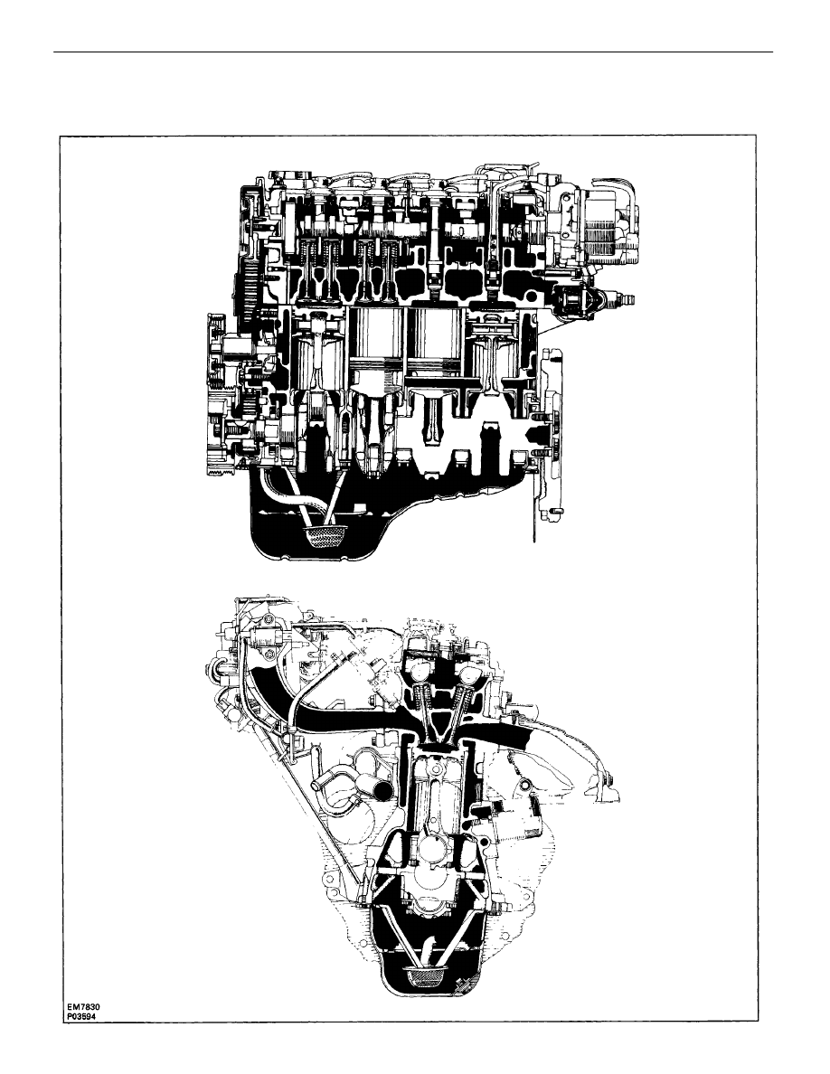
The 4A–FE engine is an in–line, 4–cylinder, 1.6 liter DOHC 16–valve engine.

ENGINE MECHANICAL

Description (4A–FE)

EM–2

The 4A–FE engine is an in–line, 4–cylinder engine with the cylinders numbered 1 – 2 – 3 – 4 from the
front. The crankshaft is supported by 5 bearings inside the crankcase. These bearings are made of aluminum
alloy.

The crankshaft is integrated with 8 weights for balance. Oil holes are placed in the center of the
crankshaft to supply oil to the connecting rods, bearing, pistons and other components.

The ignition order is 1 – 3 – 4 – 2. The cylinder head is made of aluminum alloy, with a cross flow type
intake and exhaust layout and with pent–roof type combustion chambers. The spark plugs are located in
the center of the combustion chambers.

The intake manifold has 4 independent long ports and utilizes the inertial supercharging effect to improve
engine torque at low and medium speeds.

Exhaust and intake valves are equipped with irregular pitch springs made of special valve spring carbon
steel which are capable of functioning no matter what the engine speed.

The exhaust camshaft is driven by a timing belt, and a gear on the exhaust camshaft engages with a gear
on the intake camshaft to drive it. The cam journal is supported at 5 places between the valve lifters of each
cylinder and on the front end of the cylinder head. Lubrication of the cam journals and gears is accomplished
by oil being supplied through the oiler port in the center of the camshaft.

Adjustment of the valve clearance is done by means of an outer shim type system, in which valve
adjusting shims are located above the valve lifters. This permits replacement of the shims without removal
of the camshafts.

The resin timing belt cover is made of 3 pieces. A service hole is provided in the No.1 belt cover for
adjusting the timing belt tension.

Pistons are made of high temperature–resistant aluminum alloy, and a depression is built into the piston
head to prevent interference with the valves.

Piston pins are the semi–floating type, with the pins fastened to the connecting rods by pressure fittings,
allowing the pistons and pins to float.

The No.1 compression ring is made of stainless steel and the No.2 compression ring is made of cast iron.
The oil ring is made of a combination of steel and stainless steel. The outer diameter of each piston ring
is slightly larger than the diameter of the piston and the flexibility of the rings allows them to hug the
cylinder walls when they are mounted on the piston. Compression rings No.1 and No.2 work to prevent
gas leakage from the cylinder and the oil ring works to scrape oil off the cylinder walls to prevent it from
entering the combustion chambers.

The cylinder block is made of cast iron. It has 4 cylinders which are approximately twice the length of
the piston stroke. The top of each cylinder is closed off by the cylinder head and the lower end of the
cylinders becomes the crankcase, in which the crankshaft is installed. In addition, the cylinder block
contains a water jacket, through which coolant is pumped to cool the cylinders.

The oil pan is bolted onto the bottom of the cylinder block. The oil pan is an oil reservoir made of pressed
steel sheet. A dividing plate is included inside the oil pan to keep sufficient oil in the bottom of the pan
even when the vehicle is tilted. This dividing plate also prevents the oil from making waves when the
vehicle is stopped suddenly and the oil shifts away from the oil pump suction pipe.

ENGINE MECHANICAL

Description (4A–FE)

EM–3

DESCRIPTION (3S–GTE)

The 3S–GTE engine is an in–line, 4–cylinder, 2.0 liter DOHC 16–valve engine.

ENGINE MECHANICAL

Description (3S–GTE)

EM–4

The 3S–GTE engine is an in–line, 4–cylinder engine with the cylinders numbered 1 – 2 – 3 – 4 from the
front. The crankshaft is supported by 5 bearings inside the crankcase. These bearings are made of aluminum
alloy.

The crankshaft is integrated with 8 weights for balance. Oil holes are placed in the center of the
crankshaft to supply oil to the connecting rods, bearing, pistons and other components.
The ignition order is 1 – 3 – 4 – 2. The cylinder head is made of aluminum alloy, with a cross flow type
intake and exhaust layout and with pent–roof type combustion chambers. The spark plugs are located in
the center of the combustion chambers.

The intake manifold has 8 independent long ports and utilizes the inertial supercharging effect to improve
engine torque at low and medium speeds.

Both the intake camshaft and the exhaust camshaft are driven by a single timing belt. The cam journal
is supported at 5 places between the valve lifters of each cylinder and on the front end of the cylinder head.
Lubrication of the cam journals and cams is accomplished by oil being supplied through the oiler port in
the center of the camshaft.

Adjustment of the valve clearance is done by means of an outer shim type system, in which valve
adjusting shims are located above the valve lifters. This permits replacement of the shims without removal
of the camshafts.

Pistons are made of high temperature–resistant aluminum alloy, and a depression is built into the piston
head to prevent interference with the valves.

Piston pins are the full–floating type, with the pins fastened to neither the piston boss nor the connecting
rods. Instead, snap rings are fitted on both ends of the pins, preventing the pins from falling out.

The No.1 compression ring is made of steel and the No.2 compression ring is made of cast iron. The oil
ring is made of a combination of steel and stainless steel. The outer diameter of each piston ring is slightly
larger than the diameter of the piston and the flexibility of the rings allows them to hug the cylinder walls
when they are mounted on the piston. Compression rings No.1 and No.2 work to prevent gas leakage from
the cylinder and the oil ring works to scrape oil off the cylinder walls to prevent it from entering the
combustion chambers.

The cylinder block is made of cast iron. It has 4 cylinders which are approximately twice the length of
the piston stroke. The top of each cylinder is closed off: by the cylinder head and the lower end of the
cylinders becomes the crankcase, in which the crankshaft is installed. In addition, the cylinder block
contains a water jacket, through which coolant is pumped to cool the cylinders.

The oil pan is bolted onto the bottom of the cylinder block. The oil pan is an oil reservoir made of pressed
steel sheet. A dividing plate is included inside the oil pan to keep sufficient oil in the bottom of the pan
even when the vehicle is tilted. This dividing plate also prevents the oil from making waves when the
vehicle is stopped suddenly and the oil shifts away from the oil pump suction pipe.

ENGINE MECHANICAL

Description (3S–GTE)

EM–5

DESCRIPTION (5S–FE)

The 5S–FE engine is an in–line, 4–cylinder, 2.2 liter DOHC 16–valve engine.

ENGINE MECHANICAL

Description (5S–FE)

EM–6

The 5S–FE engine is an in–line, 4–cylinder engine with the cylinders numbered 1 – 2 – 3 – 4 from the
front. The crankshaft is supported by 5 bearings inside the crankcase. These bearings are made of aluminum
alloy.

The crankshaft is integrated with 8 weights for balance. Oil holes are placed in the center of the
crankshaft to supply oil to the connecting rods, bearing, pistons and other components.

The ignition order is ”I – 3 – 4 – 2. The cylinder head is made of aluminum alloy, with a cross flow type
intake and exhaust layout and with pent–roof type combustion chambers. The spark plugs are located in
the center of the combustion chambers.

The intake manifold has 4 independent long ports and utilizes the inertial supercharging effect to improve
engine torque at low and medium speeds.

Exhaust and intake valves are equipped with irregular pitch springs made of special valve spring carbon
steel which are capable of functioning no matter what the engine speed.

The intake camshaft is driven by a timing belt, and a gear on the intake camshaft engages with a gear
on the exhaust camshaft to drive it. The cam journal is supported at 5 places between the valve lifters of
each cylinder and on the front end of the cylinder head. Lubrication of the cam journals and gears is
accomplished by oil being supplied through the oiler port in the center of the camshaft.

Adjustment of the valve clearance is done by means of an outer shim type system, in which valve
adjusting shims are located above the valve lifters. This permits replacement of the shims without removal
of the camshafts.

Pistons are made of high temperature–resistant aluminum alloy, and a depression is built into the piston
head to prevent interference with the valves.

Piston pins are the full–floating type, with the pins fastened to neither the piston boss nor the connecting
rods. Instead, snap rings are fitted on both ends of the pins, preventing the pins from falling out.

The No.1 compression ring is made of steel and the No.2 compression ring is made of cast iron. The oil
ring is made of a combination of steel and stainless steel. The outer diameter of each piston ring is slightly
larger than the diameter of the piston and the flexibility of the rings allows them to hug the cylinder walls
when they are mounted on the piston. Compression rings No.1 and No.2 work to prevent gas leakage from
the cylinder and the oil ring works to scrape oil off the cylinder walls to prevent it from entering the
combustion chambers.

The cylinder block is made of cast iron. It has 4 cylinders which are approximately twice the length of
the piston stroke. The top of each cylinder is closed off by the cylinder head and the lower end of the
cylinders becomes the crankcase, in which the crankshaft is installed. In addition, the cylinder block
contains a water jacket, through which coolant is pumped to, cool the cylinders.

The oil pan is bolted onto the bottom of the cylinder block. The oil pan is an oil reservoir made of pressed
steel sheet. A dividing plate is included inside the oil pan to keep sufficient oil in the bottom of the pan
even when the vehicle is tilted. This dividing plate also prevents the oil from making waves when the
vehicle is stopped suddenly and the oil shifts away from the oil pump suction pipe.

ENGINE MECHANICAL

Description (5S–FE)

EM–7

No fuel supply to injector:

No fuel in tank

Fuel pump not working

Fuel filter clogged

Fuel line clogged or leaking

EFI system problems

Ignition problems:

Ignition coil

Igniter

Distributor

Spark plug faulty

High–tension cords disconnected or broken

Vacuum leaks:

PCV line

EGR line

Intake manifold

T–VIS valve (3S–GTE)

Throttle body

ISC valve (3S–GTE and 5S–FE)

Brake booster line

Air suction between air flow meter and

throttle body (3S–GTE)

Low compression

Spark plug faulty

High–tension cord faulty

Ignition problems:

Ignition coil

Igniter

Distributor

Incorrect ignition timing

TROUBLESHOOTING

ENGINE OVERHEATING

Inspect coil

Inspect igniter

Inspect distributor

Reset timing

Inspect plugs

Inspect cords

Repair as necessary

Troubleshoot cooling system

Reset timing

Engine will not start/

hard to start

(cranks OK)

Cooling system faulty

Incorrect ignition timing

IG–8

, 13, 17

IG–9

, 14, 19

IG–9

, 13, 18

IG–25

, 29, 37

Repair as necessary

Perform spark test

Engine will not crank

or cranks slowly

Rough idle, stalls or

misses

HARD STARTING

Troubleshoot starting system

CO–5

IG–25

, 29, 37

Inspect plugs

Inspect cords

ROUGH IDLING

Troubleshoot EFI system

IG–7

, 11, 16

IG–7

, 11, 16

IG–7

, 11, 16

IG–7

,11,16

Starting system faulty

Repair as necessary

Check compression

Engine overheats

Possible cause

Possible cause

Possible cause

IG–6

,10,15

Problem

Remedy

Problem

Problem

Remedy

Remedy

EM–31

Page

Page

Page

FI–13

ST–2

Vacuum leaks:

PCV line

EGR line

Intake manifold

Repair as necessary

ENGINE MECHANICAL

Troubleshooting

EM–8

Spark plug faulty

High–tension cord faulty

Vacuum leaks:

PCV line

EGR line

Intake manifold

T–VIS valve (3S–GTE)

Throttle body

ISC valve (3S–GTE and 5S–FE)

Brake booster line

Air suction between air flow meter

and throttle body (3S–GTE)

Incorrect ignition timing

Incorrect valve clearance

Fuel system clogged

Air cleaner clogged

EFI system problems

Emission control system problems:

(cold engine)

EGR system always on

Engine overheats

Low compression

Vacuum leaks (cont’d):

T–VIS valve (3S–GTE)

Throttle body

ISC valve (5S–FE and 3S–GTE)

Brake booster line

Air suction between air flow meter and

throttle body (3S–GTE)

Incorrect idle speed

Check ISC system

(3S–GTE and 5S–FE)

Reset timing

Adjust valve clearance

Check fuel system

Check air cleaner

Repair as necessary

Incorrect valve clearance

EFI system problems

Engine overheats

Low compression

ENGINE HESITATES/POOR ACCELERATION

Check EGR system

Check cooling system

Check compression

Inspect plugs

Inspect cords

Repair as necessary

ROUGH IDLING (Cont’d)

EC–9

, 22, 38

CO–5

EM–31

Rough idle, stalls or

misses (Cont’d)

Engine hesitates/

poor acceleration

IG–25

, 29, 37

EM–13

,17,22

MA–8

EM–13

,17,22

IG–7

, 11, 16

IG–7

, 11, 16

Repair as necessary

Possible cause

Possible cause

CO–5

EM–31

FI–208

, 211

Problem

Remedy

Problem

Remedy

Page

Page

MA–5

Adjust idle speed (4A–FE)

Adjust valve clearance

Repair as necessary

Check cooling system

Check compression

ENGINE MECHANICAL

Troubleshooting

EM–9


Content   ..    1  2   ..