4A–FE engine is an in–line, 4–cylinder, 1.6 liter DOHC 16–valve engine. Manual - part 22
 

  Index      Manuals     4A–FE engine is an in–line, 4–cylinder, 1.6 liter DOHC 16–valve engine. Repair Manual


Search            


Content   ..  20  21  22  23   ..


4A–FE engine is an in–line, 4–cylinder, 1.6 liter DOHC 16–valve engine. Manual - part 22


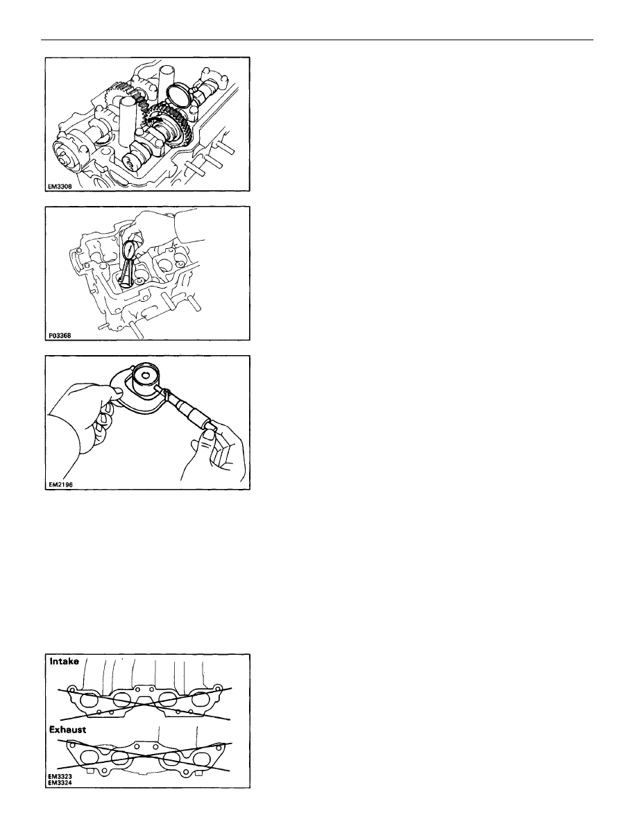
H. Inspect camshaft gear backlash

(a) Install the camshafts without installing the exhaust

cam sub–gear.
(See step 4 on pages 

EM–175

 to 177)

(b) Using a dial indicator, measure the backlash.
Standard backlash: 0.020 – 0.200 mm

(0.0008 – 0.0079 in.)

Maximum backlash: 0.30 mm (0.0188 in.)
If the backlash is greater than maximum, replace the
camshafts.

11. INSPECT VALVE LIFTERS AND LIFTER BORES

(a) Using a caliper gauge, measure the lifter bore diame-

ter of the cylinder head.

Lifter bore diameter: 31.000 – 31.018 mm

(1.2205 – 1.2213 in.)

(c) Subtract the lifter diameter measurement from the

lifter bore diameter measurement.

Standard oil clearance: 0.024 – 0.052 mm

(0.0009 – 0.0020 in.)

Maximum oil clearance: 0.07 mm (0.0028 in.)
If the oil clearance is greater than maximum, replace
the lifter. If necessary, replace the cylinder head.

12. INSPECT MANIFOLDS

Using precision straight edge and feeler gauge, mea-
sure the surface contacting the cylinder head for warp-
age.
Maximum warpage: 0.30 mm (0.0118 in.)
If warpage is greater than maximum, replace the man-
ifold.

(b) Using a micrometer, measure the lifter diameter.
Lifter diameter: 30.966 –.976 mm

(1.2191 – 1.2195 in.)

ENGINE MECHANICAL

Cylinder Head (5S–FE)

EM–170

ASSEMBLY OF CYLINDER HEAD

(See page 

EM–150

)

HINT:

Thoroughly clean all parts to be assembled.

Before installing the parts, apply new engine oil
to all
sliding and rotating surfaces.

Replace all gaskets and oil seals with new
ones.

(b) Install the following parts:

(1) Valve
(2) Spring seat
(3) Valve spring
(4) Spring retainer

(c) Using SST, compress the valve spring and place

the two keepers around the valve stem.

SST 09202–70010

1. INSTALL VALVES

(a) Using SST, push in a new oil seal.
SST 09201–41020

HINT: The intake valve oil seal is brown and the
exhaust valve oil seal is black.

ENGINE MECHANICAL

Cylinder Head (5S–FE)

EM–171

2. INSTALL VALVE LIFTERS AND SHIMS

(a) Install the valve lifter and shim.
(b) Check that the valve lifter rotates smoothly by hand.

(d) Using a plastic–faced hammer, lightly tap the

valve stem tip to assure proper fit.

ENGINE MECHANICAL

Cylinder Head (5S–FE)

EM–172

INSTALLATION OF CYLINDER HEAD

(See page 

EM–150

)

1. INSTALL CYLINDER HEAD
A. Place cylinder head on cylinder block

(a) Place a new cylinder head gasket in position on the

cylinder block.

NOTICE: Be careful of the installation direction.

(b) Place the cylinder head in position on the cylinder

head gasket.

B. Install cylinder head bolts

HINT:

The cylinder head bolts are tightened in two progres-
sive steps (steps (b) and (d)).

If any cylinder head bolt is broken or deformed, re-
place it.

(a) Apply a light coat of engine oil on the threads and

under the heads of the cylinder head bolts.

(b) Install the plate washer to each cylinder head bolt.
(c) Install and uniformly tighten the ten cylinder head

bolts in several passes in the sequence shown.

Torque: 49 N–m (500 kgf–cm, 36 ft–lbf)

If any one of the cylinder head bolts does not meet the
torque specification, replace the cylinder head bolt.

(e) Retighten the cylinder head bolts 90

°

 in the nu-

merical order shown.

(f) Check that the painted mark is now at a 90

°

 angle

to front.

(d) Mark the front of the cylinder head bolt head with

paint.

ENGINE MECHANICAL

Cylinder Head (5S–FE)

EM–173

2. INSTALL SPARK PLUG TUBES

(a) Clean the cylinder head tube holes of any residual

adhesive, oil or foreign particles. Remove any oil
with kerosene or gasoline.

(b) Screw the threads of the spark plug tube coated

with adhesive into the cylinder head.

(c) Using the spark plug tube nut and a.30 mm socket

wrench, tighten the spark plug tubes.

Torque: 39 N–m (400 kgf–cm, 29 ft–lbf)

(d) Insert a service bolt (A) into the service hole of the

camshaft sub–gear.

(e) Using a screwdriver, align the holes of the cam-

shaft drive gear and sub–gear by turning cam-
shaft sub–gear clockwise, and install a service
bolt (B).

NOTICE: Be careful not to damage the camshaft.

(b) Install the following parts:

(1) Camshaft gear spring
(2) Camshaft sub–gear
(3) Wave washer

HINT: Align the pins on the gears with the spring
ends.

3. ASSEMBLE EXHAUST CAMSHAFT

(a) Mount the hexagon wrench head portion of the

camshaft in a vise.

NOTICE: Be careful not to damage the camshaft.

(c) Using snap ring pliers, install the snap ring.

ENGINE MECHANICAL

Cylinder Head (5S–FE)

EM–174

A. Install intake camshaft

(a) Apply MP grease to the thrust portion of the

camshaft.

(b) Place the intake camshaft at 80 – 115

°

 BTDC of

camshaft angle on the cylinder head.

HINT: The above angle allows the No.1 and No.3
cylinder cam lobes of the intake camshaft to push their
valve lifters evenly.

4. INSTALL CAMSHAFTS

NOTICE: Since the thrust clearance of the camshaft
is small, the camshaft must be kept level while it is

being installed. If the camshaft is not kept level, the

portion of the cylinder head receiving the shaft thrust

may crack or be damaged, causing the camshaft to

seize or break. To avoid this, the following steps

should be carried out.

(e) Apply a light coat of engine oil on the threads and

under the heads of the bearing cap bolts.

(f) Install and uniformly tighten the ten bearing cap

bolts in several passes in the sequence shown.

Torque: 19 N–m (190 kgf–cm, 14 ft–lbf)

(c) Apply seal packing to the No.1 bearing cap as

shown.

Seal packing: Part No. 08826–00080 or equivalent

(d) Install the bearing caps in their proper locations.

ENGINE MECHANICAL

Cylinder Head (5S–FE)

EM–175

(b) Apply MP grease to the thrust portion of the cam-

shaft.

(c) Engage the exhaust camshaft gear to the intake

camshaft gear by matching the timing marks on
each gear.

(d) Roll down the exhaust camshaft onto the bearing

journals while engaging gears with each other.

NOTICE: There are also assembly reference

marks on each gear as shown in the illustration.

Do not use these marks.

(e) Turn the intake camshaft clockwise or counter-

clockwise little by little until the exhaust cam-
shaft sits in the bearing journals evenly without
rocking the camshaft on the bearing journals.

NOTICE: It is very important to replace the cam-

shaft in the bearing journals evenly while tighten-

ing bearing caps in the subsequent steps.

(f) Install the bearing caps in their proper locations.

B. Install exhaust camshaft

(a) Set the knock pin of the intake camshaft at 10 –45*

BTDC of camshaft angle.

HINT: The above angle allows the No.2 and No.4
cylinder cam lobes of the exhaust camshaft to push
their valve lifters evenly.

(h) Using SST, tap in the oil seal.

SST 09223–46011

(g) Apply MP grease to a new oil seal lip.

ENGINE MECHANICAL

Cylinder Head (5S–FE)

EM–176

5. CHECK AND ADJUST VALVE CLEARANCE

(See page 

EM–22

)

Turn the camshaft and position the cam lobe upward,
and check and adjust the valve clearance.
Valve clearance (Cold):

Intake 0.19 – 0.29 mm (0.007 – 0.011 in.)
Exhaust 0.28 – 0.38 mm (0.011 – 0.015 in.)

6. INSTALL SEMI–CIRCULAR PLUGS

(a) Remove any old packing (FIPG) material.
(b) Apply seal packing to the semi–circular plug

grooves.

Seal packing: Part No. 08826–00080 or equivalent

(g) Apply a light coat of engine oil on the threads and

under the heads of the bearing cap bolts.

(h) Install and uniformly tighten the ten bearing cap

bolts in several passes in the sequence shown.

Torque: 19 N–m (190 kgf–cm, 14 ft–lbf)

(c) Install the two semi–circular plugs to the cylinder

head.

(i) Remove the service bolt (B).

ENGINE MECHANICAL

Cylinder Head (5S–FE)

EM–177


Content   ..  20  21  22  23   ..