4A–FE engine is an in–line, 4–cylinder, 1.6 liter DOHC 16–valve engine. Manual - part 17
 

  Index      Manuals     4A–FE engine is an in–line, 4–cylinder, 1.6 liter DOHC 16–valve engine. Repair Manual


Search            


Content   ..  15  16  17  18   ..


4A–FE engine is an in–line, 4–cylinder, 1.6 liter DOHC 16–valve engine. Manual - part 17


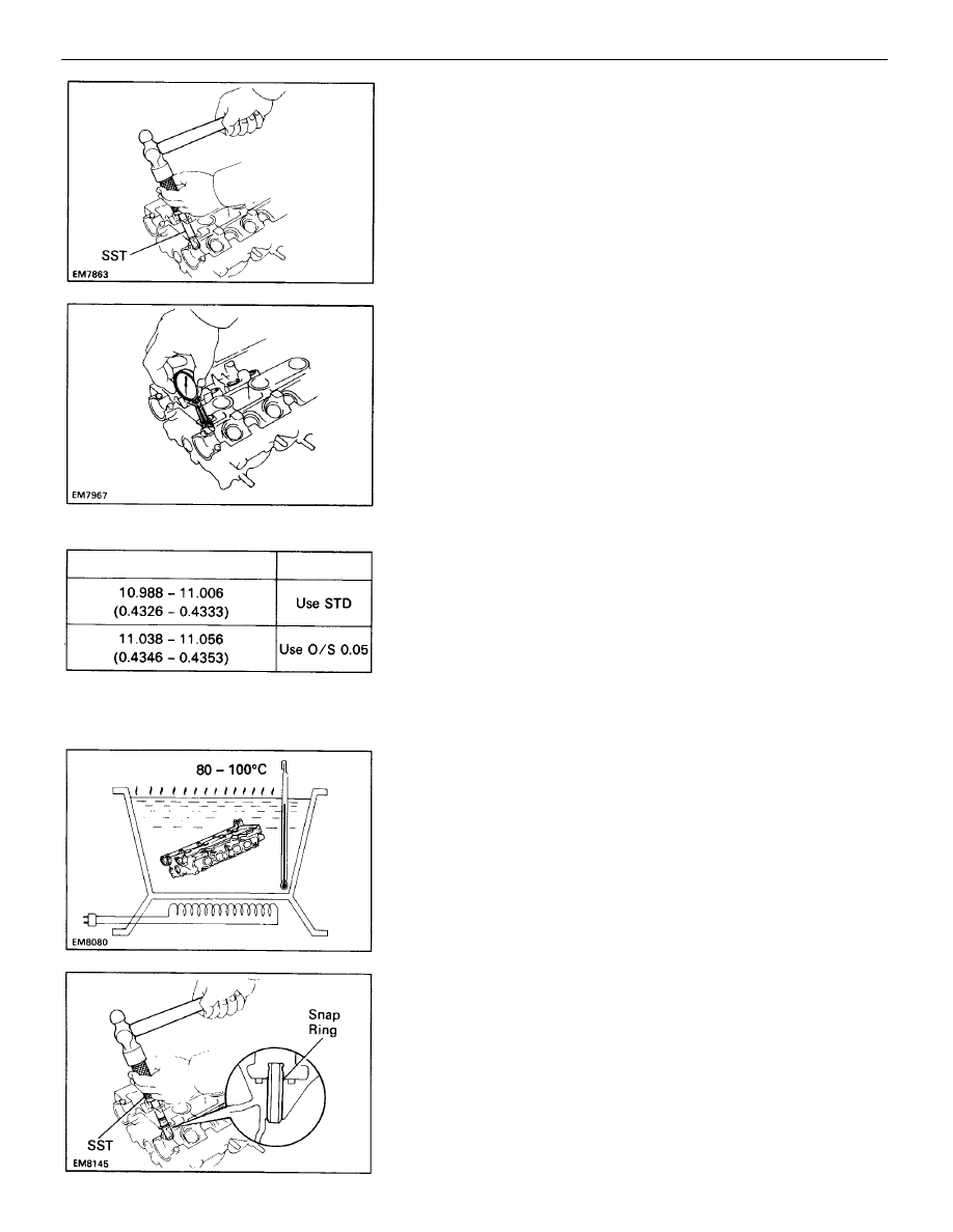
(e) Select a new guide bushing (STD or O/S 0.05).

If the bushing bore diameter of the cylinder
head is greater than 11.006 mm (0.4333 in.),
machine the bushing bore to the following di-
mension:

11. 038 –11.056 mm (0.4346 – 0.4353 in.)

If the bushing bore diameter of the cylinder
head is greater than 11.056 mm (0.4353 in.), re-
place the cylinder head.

(g) Using SST and a hammer, tap in a new guide

bushing until the snap ring makes contact with
the cylinder head.

SST 09201–70010

(c) Using SST and a hammer, tap out the guide

bushing.

SST 09201–70010

(d) Using a caliper gauge, measure the bushing

bore diameter of the cylinder head.

(f) Gradually heat the cylinder head to 80–100

°

C

(176–212

°

F).

Bushing bore diameter mm* (in.)

Both intake and exhaust

Bushing size

ENGINE MECHANICAL

Cylinder Head (3S–GTE)

EM–130

(d) Check the valve overall length.
Standard overall length:

Intake 

100.50 mm (3.9567 in.)

Exhaust 

99.55 mm (3.9193 in.)

Minimum overall length:

Intake 

99.80 mm (3.9291 in.)

Exhaust 

98.85 mm (3.8977 in.)

If the overall length is less than minimum, replace
the valve.

(c) Check the valve head margin thickness.
Standard margin thickness: 0.8 –1.2 mm

(0.031 – 0.047 in.)

Minimum margin thickness: 0.5 mm (0.020 in.)
If the margin thickness is less than minimum, re-
place the valve.

7. INSPECT AND GRIND VALVES

(a) Grind the valve enough to remove pits and carbon.
(b) Check that the valve is ground to the correct valve

face angle.

Valve face angle: 44.5

°

(e) Check the surface of the valve stem tip for wear.

If the valve stem tip is worn, resurface the tip with
a grinder or replace the valve.

NOTICE: Do not grind off more than minimum.

(h) Using a sharp 6 mm reamer, ream the guide

bushing to obtain the standard specified clear-
ance (See page 

EM–129

) between the guide

bushing and valve stem.

ENGINE MECHANICAL

Cylinder Head (3S–GTE)

EM–131

(b) Check the valve seating position. Apply a light

coat of prussian blue (or white lead) to the valve
face. Lightly press the valve against the seat.
Do not rotate the valve.

(c) Check the valve face and seat for the following:

If blue appears 360

°

 around the face, the

valve is concentric. If not, replace the
valve.

If blue appears 360

°

 around the valve

seat, the guide and face are concentric. If
not, resurface the seat.

Check that the seat contact is in the middle
of the valve face with the following width:
1.0 –1.4 mm (0.039 – 0.055 in.)

8. INSPECT AND CLEAN VALVE SEATS

(a) Using a 45

°

 carbide cutter, resurface the valve seats.

Remove only enough metal to clean the seats.

If not, correct the valve seats as follows:
(1) If the seating is too high on the valve face,

use


30

°

 and 45

°

 cutters to correct the seat.

(2) If the seating is too low on the valve face, use

75

°

 and 45

°

 cutters to correct the seat.

ENGINE MECHANICAL

Cylinder Head (3S–GTE)

EM–132

10. INSPECT CAMSHAFTS AND BEARINGS
A. Inspect camshaft for runout

(a) Place the camshaft on V–blocks.
(b) Using a dial indicator; measure the circle runout at

the center journal.

Maximum circle runout: 0.06 mm (0.0024 in.)
If the circle runout is greater than maximum, replace the
camshaft.

(c) Using a spring tester, measure the tension of the

valve spring at the specified installed length.

Installed tension:

201 – 236 N (20.5 – 24.1 kgf, 45.2 – 53.1 lbf )
at 34.4 mm (1.354 in.)

If the installed tension is not as specified, replace
the valve spring.

9. INSPECT VALVE SPRINGS

(a) Using a steel square, measure the squareness of the

valve spring.

Maximum squareness: 2.0 mm (0.079 in.)
If the squareness is greater than maximum, replace the
valve spring.

(b) Using a vemier caliper, measure the free length

of the valve spring.

Free length: 44.43 mm (1.7492 in.)
If the free length is not as specified, replace the
valve spring.

(d) Hand–lap the valve and valve seat with an abra-

sive compound.

(e) After hand–lapping, clean the valve and valve

seat.

ENGINE MECHANICAL

Cylinder Head (3S–GTE)

EM–133

B. Inspect cam lobes
Using a micrometer, measure the cam lobe height.
Standard cam lobe height:

Intake 

41.010 – 41.110 mm
(1.6146 – 1.6185 in.)

Exhaust 

41.090 – 41.190 mm
(1.6177 – 1.6217 in.)

Minimum cam lobe height:

Intake 

39.90 mm (1.5709 in.)

Exhaust 

39.98 mm (1.5740 in.)

If the cam lobe height is less than minimum, replace
the camshaft.

C. Inspect camshaft journals

Using a micrometer, measure the journal diameter.
Journal diameter: 26.959 – 26.975 mm

(1.0614 – 1.0620 in)

If the journal diameter is not as specified, check the oil
clearance.

E. Inspect camshaft journal oil clearance

(a) Clean the bearing caps and camshaft journals.
(b) Place the camshafts on the cylinder head.
(c) Lay a strip of Plastigage across each of the camshaft

journals.

D. Inspect camshaft bearings

Check the bearings for flaking and scoring.
If the bearings are damaged, replace the bearing caps
and cylinder head as a set.

(d) Install the bearing caps.

(See step 2 on page 

EM–141

)

Torque: 19 N–m (190 kgf–cm, 14 ft–lbf) 

NOTICE: Do not turn the camshaft.

ENGINE MECHANICAL

Cylinder Head (3S–GTE)

EM–134

F. Inspect camshaft thrust clearance

(a) Install the camshafts.

(See step 2 on page 

EM–141

)

(b) Using a dial indicator, measure the thrust clearance

while moving the camshaft back and forth.

Standard thrust clearance: 0.120 – 0.240 mm

(0.0047 – 0.0094 in.)

Maximum thrust clearance: 0.30 mm (0.0118 in.)
If the thrust clearance is greater than maximum, replace
the camshaft. If necessary, replace the bearing caps and
cylinder head as a set.

11. INSPECT VALVE LIFTERS AND LIFTER BORES

(a) Using a caliper gauge, measure the lifter bore diameter

of the cylinder head.

Lifter bore diameter: 37.000 – 31.021 mm

(1.2205 – 1.2213 in.)

(f) Measure the Plastigage at its widest point.
Standard oil clearance: 0.025 – 0.062 mm

(0.0010 – 0.0024 in.)

Maximum oil clearance: 0.08 mm (0.0031 in.)
If the oil clearance is greater than maximum, replace
the camshaft. If necessary, replace the bearing caps
and cylinder head as a set.
(g) Completely remove the Plastigage.

(b) Using a micrometer, measure the lifter diameter.
Lifter diameter: 30.975 – 30.985 mm

0.2195 – 1.2199 in.)

(e) Remove the bearing caps.

ENGINE MECHANICAL

Cylinder Head (3S–GTE)

EM–135

12. INSPECT MANIFOLDS

(Intake manifold)
Using precision straight edge and feeler gauge, mea-
sure the surface contacting the T–VIS valve for warp-
age.
Maximum warpage: 0.20 mm (0.0079 in.)
If warpage is greater than maximum, replace the intake
manifold.

(c) Subtract the lifter diameter measurement from

the lifter bore diameter measurement.

Standard oil clearance: 0.015 – 0.046 mm

(0.0005 – 0.0018 in.)

Maximum oil clearance: 0.07 mm (0.0028 in.)
If the oil clearance is greater than maximum, re-
place the lifter. If necessary, replace the cylinder
head.

(Exhaust manifold)
Using precision straight edge and feeler gauge,
measure the surface contacting the cylinder head
for warpage.
Maximum warpage: 0.20 mm (0.0079 in.)
If warpage is greater than maximum, replace the
exhaust manifold.

ENGINE MECHANICAL

Cylinder Head (3S–GTE)

EM–136

INSPECTION OF TOYOTA–VARIABLE
INDUCTION SYSTEM (T–VIS)
COMPONENTS

1. INSPECT T–VIS VALVE
A. Inspect for flatness

Using precision straight edge and feeler gauge, measure
the surfaces contacting the cylinder head and intake
manifold for warpage.
Maximum warpage: 0.20 mm (0.0079 in.)
If warpage is greater than maximum, replace the T–VIS
valve.

B. Inspect for operation

(a) With 53.3 kPa (400 mmHg, 15.75 in.Hg) of vacuum

applied to the actuator, check that the control valve
moves smoothly to the fully closed position.

(b) With the vacuum released, check that the control

valve fully opens quickly.

If operation is not as specified, replace the T–VIS valve.

2. INSPECT VACUUM TANK

(a) Check that air flows from ports A to B.
(b) Check that air does not flow from ports B to A.

(c) Apply 67.7 kPa (500 mmHg, 19.69 in.Hg) of vacu-

um to port A, and check that there is no change

in vacuum after one minute.

If operation is not as specified, replace the vacuum
tank.

3. INSPECT T–VIS VSV (See page 

FI–203

)

ENGINE MECHANICAL

Cylinder Head (3S–GTE)

EM–137


Content   ..  15  16  17  18   ..