Toyota Automatic Transmission A340 Series. Repair Manual - part 29
AT1473
AT1469
AT1472
AT7977
AT4852
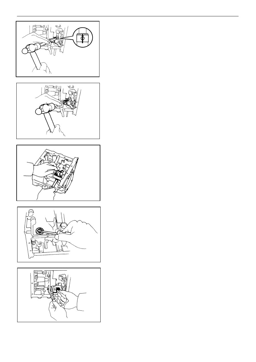
2.
REMOVE TRANSFER MANUAL VALVE LEVER AND
SHAFT
(a)
Using a chisel, cut off the spacer and remove it
from the shaft.
(b)
Using a pin punch and hammer, drive out the pin.
(c)
Slide the shaft out through the case and remove
the manual valve lever.
(d)
Using a screwdriver, remove the oil seal from the
case.
3.
REMOVE SPRING, SHAFT AND PARKING LOCK
PAWL
(a)
Remove the spring, shaft and parking lock pawl.
(b)
Remove the E−ring from the shaft.
−
AUTOMATIC TRANSMISSION (A340H)
Component Parts (Transfer Case and Front Support)
AT−221