Toyota Automatic Transmission A340 Series. Repair Manual - part 25
 

  Index      Toyota     Toyota Automatic Transmission A340 Series. Repair Manual


Search            copyright infringement  


Content   ..  23  24  25  26   ..


Toyota Automatic Transmission A340 Series. Repair Manual - part 25


AT3149

AT8228

AT8402

AT8157

AT8424

(e)

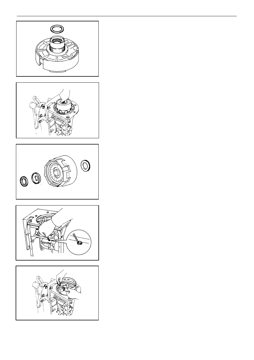
Remove the race.

49. REMOVE DIRECT CLUTCH WITH FORWARD CLUTCH

(a)

Remove the direct clutch with the forward clutch

from the case.

(b)

Remove the two bearings and race.

54. REMOVE SECOND COAST BRAKE BAND

(a)

Remove the E−ring from the pin.

(b)

Remove the pin from the brake band.

(c)

Remove the second coast brake band from the

case.

For the method of inspection, refer to  AT−76.

AUTOMATIC TRANSMISSION (A340H)

Removal of Component Parts

AT−189

AT8423

AT8422

E7131

AT8175

AT8229

51. REMOVE FRONT PLANETARY GEAR UNIT

(a)

Remove the race.

(b)

Remove the front planetary ring gear from the case.

(c)

Remove the bearing and race.

(d)

Remove the race.

(e)

With wooden blocks under the output shaft, stand

the transmission on the output shaft.

AT−190

AUTOMATIC TRANSMISSION (A340H)

Removal of Component Parts

AT8186

AT8419

E7135

AT8420

AT8421

SST

(f)

Using SST, remove the snap ring.

SST

09350−30020 (09350−07070)

(g)

Remove the front planetary gear from the case.

(h)

Remove the bearing and race from the front plan-

etary gear.

52. REMOVE PLANETARY SUN GEAR WITH NO. 1

ONE−WAY CLUTCH

53. CHECK PACK CLEARANCE OF SECOND BRAKE

Using a feeler gauge, measure the clearance between

the snap ring and flange as shown in the figure.

Clearance: 0.62 − 1.98 mm (0.0244 − 0.0780 in.)

If the values are nonstandard, inspect the discs.

(See page  AT−84)

AUTOMATIC TRANSMISSION (A340H)

Removal of Component Parts

AT−191

AT8417

AT8222

AT8223

AT8416

AT8418

54. REMOVE FLANGE, PLATES AND DISCS OF SECOND

BRAKE
(a)

Remove the snap ring.

(b)

Remove the flange, plates and discs as a set.

HINT: One flange, five plates and five discs

55. REMOVE PARKING LOCK ROD

Disconnect the parking lock rod from the manual valve

lever.

56. CHECK PACK CLEARANCE OF FIRST AND 

REVERSE BRAKE
Using a feeler gauge, measure the clearance between

the plate and second brake drum as shown in the figure.

Clearance: 0.58 − 1.92 mm (0.0228 − 0.0756 in.)

If the values are nonstandard, inspect the discs.

(See page  AT−86)

57. REMOVE SECOND BRAKE PISTON SLEEVE

AT−192

AUTOMATIC TRANSMISSION (A340H)

Removal of Component Parts

AT8415

AT8414

AT8183

AT8208

AT4443

58. REMOVE REAR PLANETARY GEAR UNIT WITH SEC-

OND BRAKE DRUM, FIRST AND REVERSE BRAKE

PACK AND OUTPUT SHAFT
(a)

Using two screwdrivers, remove the snap ring.

(b)

Remove the rear planetary gear, second brake

drum, first and reverse brake pack and output

shaft as an assembly.

(c)

Remove the assembled thrust bearing and race

from the case.

(d)

Remove the second brake drum assembly.

(e)

Remove the cushion plate, flange, plates and discs

of the first and reverse brake.

HINT: One cushion plate, one flange, seven plates and

six discs

For the method of inspection, refer to  AT−86.

AUTOMATIC TRANSMISSION (A340H)

Removal of Component Parts

AT−193

AT5107

AT4445

AT8336

SST

Snap Ring

AT4446

AT4444

59. REMOVE BRAKE DRUM GASKET

60. REMOVE LEAF SPRING

61. CHECK FIRST AND REVERSE BRAKE PISTONS

MOVING
Make sure the first and reverse brake pistons move

smoothly when applying and releasing the compressed

air into the transmission case.

62. REMOVE COMPONENTS OF FIRST AND REVERSE

BRAKE PISTON
(a)

Set SST on the spring retainer, and compress the

return spring.

SST

09350−30020 (09350−07050)

(b)

Remove the snap ring with snap ring pliers.

(c)

Remove the piston return spring.

(d)

Hold No. 2 first and reverse brake piston with hand,

apply compressed air to the transmission case to

remove No. 2 first and reverse brake piston.

(e)

Remove No. 2 first and reverse brake piston.

If the piston does not pop out with compressed air, lift the

piston out with needle−nose pliers.
(f)

Remove the O−ring from No. 2 piston.

AT−194

AUTOMATIC TRANSMISSION (A340H)

Removal of Component Parts

AT8225

AT8236

AT8335

SST

AT1636

AT8334

SST

(g)

Install SST behind the reaction sleeve and gradu-

ally lift it out of the transmission case.

SST

09350−30020 (09350−07080)

(h)

Remove the O−ring from the reaction sleeve.

(i)

Install SST behind No. 1 brake piston and gradu-

ally lift it out of the transmission case.

SST

09350−30020 (09350−07090)

(j)

Remove the two O−rings from No. 1 piston.

63. REMOVE MANUAL VALVE LEVER, SHAFT AND OIL

SEALS
(a)

Using a chisel, cut off the spacer and remove it

from the shaft.

(b)

Using a pin punch, drive out the pin.

(c)

Pull the manual valve lever shaft out through the

case, and remove the lever.

(d)

Using a screwdriver, remove the two oil seals.

AUTOMATIC TRANSMISSION (A340H)

Removal of Component Parts

AT−195

AT7974

SST

AT7970

AT3195

♦ Non−reusable part

Plate

Flange

Piston

Disc

Snap Ring

♦ O−Ring

Snap Ring

Transfer Direct Clutch Drum

♦ O−Ring

Piston Return Spring

COMPONENT PARTS (A340H)

Transfer Direct Clutch

COMPONENTS

DISASSEMBLY OF TRANSFER DIRECT CLUTCH

1.

CHECK PISTON STROKE OF TRANSFER DIRECT

CLUTCH
(a)

Install the direct clutch onto the transfer front sup-

port.

(b)

Place SST and a dial indicator onto the transfer

direct clutch piston as shown in the figure.

SST

09350−30020 (09350−06120)

AT−196

AUTOMATIC TRANSMISSION (A340H)

Component Parts (Transfer Direct Clutch)


Content   ..  23  24  25  26   ..