Toyota FJ Cruiser (GSJ 10, 15 series). Instruction - part 437


  Index      Toyota     Toyota FJ Cruiser (model GSJ 10, 15 series) - service repair instruction 2007 year


Search            copyright infringement  


Content   ..  435  436  437  438   ..


Toyota FJ Cruiser (GSJ 10, 15 series). Instruction - part 437


SEAT BELT  –  SEAT BELT WARNING SYSTEM

SB–15

SB

2.

CENTER AIRBAG SENSOR ASSEMBLY

3.

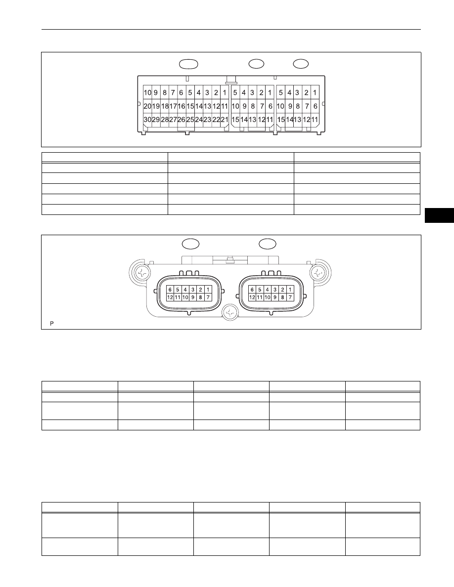
OCCUPANT CLASSIFICATION ECU

(a) Disconnect the Q4 occupant classification ECU 

connector.

(b) Measure the voltage and resistance of the wire 

harness side connector.

Standard:

If the result is not as specified, there may be a 
malfunction in the wire harness.

(c) Reconnect the occupant classification ECU 

connector.

(d) Measure the resistance of the wire harness side 

connector.

Standard:

Terminal No.

Terminal Symbol

Destination

E29-13

PBEW

Combination meter assembly

E29-21

IG2

IGN fuse

E29-25

E1

Ground

K1-12

FSP+

Occupant Classification ECU

K1-13

FSP-

Occupant Classification ECU

L1

K1

E29

C141045E01

Q4

Q5

H100909E12

Symbols (Terminals No.)

Wiring Color

Terminal Description

Condition

Specified Condition

Q4-1 (+B) - Body ground

W-R - Body ground

Battery

Always

11 to 14 V

Q4-3 (GND) - Body 

ground

W-B - Body ground

Ground

Always

Below 1 

Q4-7 (IG) - Body ground

B-O - Body ground

Ignition switch signal

Ignition switch OFF 

→ ON

Below 1 V 

→ 11 to 14 V

Symbols (Terminal No.)

Wiring Color

Terminal Description

Condition

Specified Condition

Q4-4 (FSR-) - Q4-3 (GND)

B - W-B

Center airbag sensor 

assembly communication 

line (-)

Always

Below 1 

Q4-5 (BGND) - Q4-3 

(GND)

GR - W-B

Passenger side buckle 

switch ground line

Always

Below 1 

SB–16

SEAT BELT  –  SEAT BELT WARNING SYSTEM

SB

If the result is not as specified, there may be a 
malfunction in the wire harness.

Q4-8 (FSR+) - Q4-4 (FSR-

)

W - B

Center airbag sensor 

assembly communication 

line

Ignition switch ON

Pulse generation

Q4-9 (BSW) - Q4-5 

(BGND)

L - GR

Passenger side buckle 

switch line

Buckle switch ON

Buckle switch OFF

Pulse generation

Symbols (Terminal No.)

Wiring Color

Terminal Description

Condition

Specified Condition

SEAT BELT  –  SEAT BELT WARNING SYSTEM

SB–17

SB

4.

MAIN BODY ECU (Driver Side J/B)

1

2

3

4

5

6

11

12

13

14

15

16

7

8

9

10

17

18

19

20

1

2

3

4

5

6

9

10

11

12

13

14

7

8

15

16

1

2

3

4

5

6

13

14

7

8

15

16

17

18

19

20

9

10

21

22

11

12

23

24

1

2

3

4

5

6

7

8

9

10

11

12

13

10

6

9

5

6

5

8

4

4

7

3

3

6

2

2

5

1

1

4

16

3

15

2

14

1

13

22

12

30

29

18

17

28

27

26

25

24

23

21

11

20

10

19

9

18

17

8

7

17

16

15

14

13

12

11

10

9

8

16

15

14

13

24

7

23

22

21

26

25

24

12

11

20

23

19

21

20

19

18

22

1

2

3

4

5

6

1

2

E6

1A

1B

1D

1F

1E

1C

E7

E8

E6

1A

1B

1D

1F

1E

1C

E7

E8

Main Body ECU (Driver Side J/B):

Left View:

Rear View:

B136051E03

SB–18

SEAT BELT  –  SEAT BELT WARNING SYSTEM

SB

(a) Disconnect the 1A, 1B and 1H main body ECU 

(driver side J/B) connectors.

1

2

4

3

1

2

3

4

5

6

7

8

9 10 11 12 13 14

15 16

1

17

2

18

3

19

4

20

5

21

6

22

7

23

8

24

9

25

10

26

11

27

12

28

13

29

14

30

15

31

16

32

1

17

2

18

3

19

4

20

5

21

6

22

7

23

8

24

9

25

10

26

11

27

12

28

13

29

14

30

15

31

16

32

1

2

3

4

1

13

2

14

3

15

4

16

5

17

6

18

19 20

7

9

21

10

22

11

23

12

24

1

2

3

4

5

6

8

1G

1L

1K

1J

1H

1G

1H

1L

1J

1K

Main Body ECU (Driver Side J/B):

Front View:

B136052E03


Content   ..  435  436  437  438   ..