Toyota FJ Cruiser (GSJ 10, 15 series). Instruction - part 280


  Index      Toyota     Toyota FJ Cruiser (model GSJ 10, 15 series) - service repair instruction 2007 year


Search            copyright infringement  


Content   ..  278  279  280  281   ..


Toyota FJ Cruiser (GSJ 10, 15 series). Instruction - part 280


LIGHTING  –  LIGHTING SYSTEM

LI–17

LI

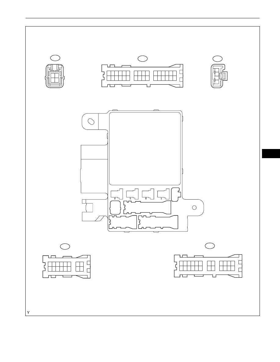
(a) Disconnect the 1A, 1B, 1E, and 1H main body ECU 

(driver side J/B) connectors.

1

2

4

3

1

2

3

4

5

6

7

8

9 10 11 12 13 14

15 16

1

17

2

18

3

19

4

20

5

21

6

22

7

23

8

24

9

25

10

26

11

27

12

28

13

29

14

30

15

31

16

32

1

17

2

18

3

19

4

20

5

21

6

22

7

23

8

24

9

25

10

26

11

27

12

28

13

29

14

30

15

31

16

32

1

2

3

4

1

13

2

14

3

15

4

16

5

17

6

18

19 20

7

9

21

10

22

11

23

12

24

1

2

3

4

5

6

8

1G

1L

1K

1J

1H

1G

1H

1L

1J

1K

Main Body ECU:

Front View:

B136052E01

LI–18

LIGHTING  –  LIGHTING SYSTEM

LI

(b) Measure the voltages and resistances of the wire 

harness side connectors.

Standard:

If the result is not as specified, there may be a 
malfunction in the wire harness.

(c) Reconnect the main body ECU (driver side J/B) 

connectors.

(d) Measure the voltages of the wire harness side 

connectors.

Standard voltage:

Symbols (Terminal No.)

Wiring Color

Terminal Description

Condition

Specified Condition

GND1 (1H-2) - Body 

ground

W-B - Body ground

Ground

Always

Below 1 

BECU (1B-4) - Body 

ground

W-R - Body ground

Power source circuit 

(From battery)

Always

11 to 14 V

BDR1 (1E-9) - Body 

ground

B-Y - Body ground

Power source circuit 

(From battery)

Always

11 to 14 V

GND2 (1A-7) - Body 

ground

W - Body ground

Ground

Always

Below 1 

Symbols (Terminal 

No.)

Wiring Color

Terminal Description

Condition

Specified Condition

SIG - (1F-8) Body 

ground

B-R - Body ground

Ignition switch signal

Ignition switch OFF

Below 1 V

Ignition switch ON

10 to 14 V

ILE (1A-8) - Body 

ground

W - Body ground

Illumination signal (To 

room light assembly)

Driver door closed

10 to 14 V

Driver door open

Below 1 V

HRLY (1B-8) - Body 

ground

Y-P - Body ground

HEAD signal (To HEAD 

relay)

Light control switch OFF or 

in TAIL

10 to 14 V

Light control switch in HEAD

Below 1 V

TRLY (1E-16) - Body 

ground

V - Body ground

TAIL signal (To TAIL relay)

Light control switch OFF

10 to 14 V

Light control switch in TAIL 

or HEAD

Below 1 V

ACC (1D-5) - Body 

ground

W-G - Body ground

Ignition switch (From 

battery) ACC signal circuit 

(To ignition switch)

Ignition switch OFF

Below 1 V

Ignition switch ACC

10 to 14 V

H-ON (1B-3)* - Body 

ground

GR-G* - Body ground

DRL signal (To DRL relay)

Light control switch OFF or 

in TAIL position and engine 

running and parking brake 

off

Below 1 V

Ignition switch OFF

10 to 14 V

LMRY (E6-3) - Body 

ground

GR-R - Body ground

DOME relay output signal 

(To DOME relay)

All doors locked

10 to 14 V

Any door open

Below 1 V

DIM* (E6-7) - Body 

ground

R-G* - Body ground

DIM relay output signal 

(To DIM relay)

Dimmer switch in FLASH or 

HIGH

Below 1 V

Dimmer switch in LOW

10 to 14 V

L* (E6-14) - Body 

ground

GR* - Body ground

Generator operate 

condition signal

Engine start Charge warning 

light ON

Below 1 V

Engine start Charge warning 

light OFF

10 to 14 V

PKB* (E7-2) - Body 

ground

W-R* - Body ground

Parking brake switch 

signal

Parking brake switch ON

Below 1 V

Parking brake switch OFF

10 to 14 V

BCTY (E7-7) - Body 

ground

W - Body ground

Back door courtesy switch 

and back window courtesy 

switch input

Back door or back window 

open

Below 1 V

Back door and back window 

closed

11 to 14 V

RLCY (E7-11) - Body 

ground

P-B - Body ground

Rear LH door courtesy 

switch input

Rear LH door open

Below 1 V

Rear LH door closed

11 to 14 V

LIGHTING  –  LIGHTING SYSTEM

LI–19

LI

HINT:
*: w/ daytime running light system
If the result is not as specified, there may be a 
malfunction in the wire harness.

RRCY (E7-12) - Body 

ground

P-L - Body ground

Rear RH door courtesy 

switch input

Rear RH door open

Below 1 V

Rear RH door closed

11 to 14 V

DCTY (E7-23) - Body 

ground

R-B - Body ground

Driver door courtesy 

switch input

Driver door open

Below 1 V

Driver door closed

11 to 14 V

PCTY (E7-24) - Body 

ground

G-Y - Body ground

Front passenger door 

courtesy switch input

Front passenger door open

Below 1 V

Front passenger door 

closed

11 to 14 V

HEAD (E8-1) - Body 

ground

R - Body ground

Light control switch 

(HEAD signal)

Light control switch OFF

11 to 14 V

Light control switch is ON

Below 1 V

HU* (E8-2) - Body 

ground

R-G* - Body ground

Headlight dimmer switch 

(HIGH signal)

Headlight dimmer switch in 

HIGH

Below 1 V

Headlight dimmer switch in 

LOW

11 to 14 V

HF (E8-7) - Body ground

R-W - Body ground

Headlight dimmer switch 

(FLASH signal)

Headlight dimmer switch in 

FLASH

Below 1 V

Headlight dimmer switch in 

LOW or HIGH

11 to 14 V

TAIL (E8-8) - Body 

ground

G - Body ground

Light control switch (TAIL 

signal)

Light control switch in TAIL

Below 1 V

Light control switch OFF

11 to 14 V

DRLP (E8-12) - Body 

ground

V-Y - Body ground

Open door warning light 

output

Open door warning light ON

Below 1.2 V

Open door warning light 

OFF

10 to 14 V

HF2 (E8-20) - Body 

ground

Y-P - Body ground

Headlight dimmer switch 

(FLASH signal)

Headlight dimmer switch in 

FLASH

Below 1 V

Headlight dimmer switch in 

LOW or HIGH

10 to 14 V

Symbols (Terminal 

No.)

Wiring Color

Terminal Description

Condition

Specified Condition

LI–20

LIGHTING  –  LIGHTING SYSTEM

LI

DATA LIST / ACTIVE TEST

1.

READ DATA LIST
HINT:
Using the intelligent tester's DATA LIST allows a switch, 
sensor, actuator and other item values to be read without 
removing any parts. Reading the DATA LIST early in 
troubleshooting is one way to save time.
(a) Connect the intelligent tester with CAN VIM to the 

DLC3.

(b) Turn the ignition switch ON.
(c) Read the DATA LIST according to the prompts 

displayed on the tester.

BODY:

2.

PERFORM ACTIVE TEST
HINT:
Performing the intelligent tester's ACTIVE TEST allows 
relays, VSV, actuators and other items to be operated 
without removing any parts. Performing the ACTIVE 
TEST early in troubleshooting is one way to save time. 
The DATA LIST can be displayed during the ACTIVE 
TEST.
(a) Connect the intelligent tester with CAN VIM to the 

DLC3.

Item

Measurement Item/Dispay 

(Range)

Normal Condition

Diagnostic Note

D DOR CTY SW

Driver door courtesy switch 

signal/ON or OFF

ON :Driver door is open
OFF: Driver door is closed

-

P DOR CTY SW

Front passenger door courtesy 

switch signal/ON or OFF

ON: Front passenger door is 
open
OFF: Front passenger door is 
closed

-

Rr DOR CTY SW

Rear door courtesy switch signal/

ON or OFF

ON: Either right or left rear door is 
open
OFF: Both right and left rear 
doors are closed

-

LUGG COURTSY SW

Back door and back window 

courtesy switch signal/ON or OFF

ON: Either back door or back 
window is open
OFF: Both back door and back 
window are closed

-

DIMMER SW

Dimmer switch signal/ON or OFF

ON: Dimmer switch is ON (High 
Beam) or High flasher switch is 
ON
OFF: Dimmer switch is OFF (Low 
Beam) or High flasher switch is 
OFF

-

HIGH FLASER  SW

High flasher switch signal/ON or 

OFF

ON: High flasher switch is ON
OFF: High flasher switch is OFF

-

HEAD LIGHT SW

Head light switch signal/ON or 

OFF

ON: Light control switch is in 
HEAD position
OFF: Light control switch is not in 
HEAD position

-

TAIL LIGHT SW

Taillight switch signal/ON or OFF

ON: Light control switch is in TAIL 
or HEAD position
OFF: Light control switch is OFF

-

ALT L SIG

Generator L terminal signal/ON or 

OFF

ON: Engine start Charge warning 
light is OFF
OFF: Engine start Charge 
warning light is ON

-


Content   ..  278  279  280  281   ..