Toyota FJ Cruiser (GSJ 10, 15 series). Instruction - part 190


  Index      Toyota     Toyota FJ Cruiser (model GSJ 10, 15 series) - service repair instruction 2007 year


Search            copyright infringement  


Content   ..  188  189  190  191   ..


Toyota FJ Cruiser (GSJ 10, 15 series). Instruction - part 190


1GR-FE ENGINE MECHANICAL  –  ENGINE UNIT

EM–191

EM

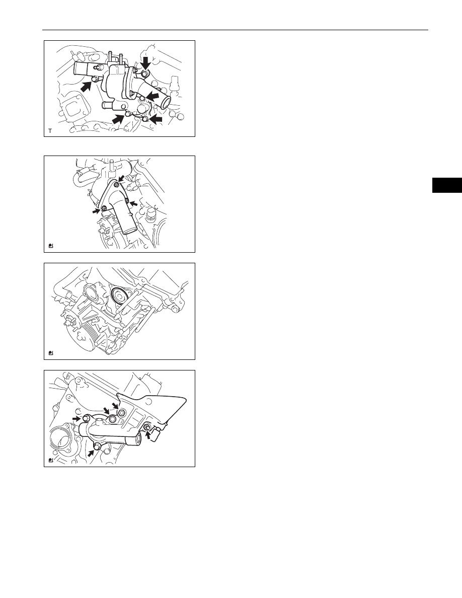
(c) Install the water inlet with the 5 bolts.

Torque: 9.0 N*m (92 kgf*cm, 80 in.*lbf)

55. INSTALL WATER BY-PASS HOSE

(a) Install the water by-pass hose with the 2 clamps.

56. INSTALL NO. 2 WATER BY-PASS HOSE

(a) Install the No. 2 water by-pass hose with the 2 

clamps.

57. INSTALL NO. 3 WATER BY-PASS HOSE

(a) Install the No. 3 water by-pass hose with the 2 

clamps.

58. INSTALL WITH THERMOSTAT WATER INLET SUB-

ASSEMBLY
(a) Install a new O-ring and the water inlet with 

thermostat with the 3 nuts.
Torque: 9.0 N*m (92 kgf*cm, 80 in.*lbf)

59. INSTALL OIL FILTER BRACKET SUB-ASSEMBLY

(a) Install the 2 stud bolts.

Torque: 10 N*m (102 kgf*cm, 7.4 ft.*lbf)

(b) Install a new gasket.

(c) Install the oil filter bracket with the 3 bolts and 2 

nuts.
Torque: 19 N*m (194 kgf*cm, 14 ft.*lbf)

A126462

A121042

A121046

A120414

EM–192

1GR-FE ENGINE MECHANICAL  –  ENGINE UNIT

EM

60. INSTALL ENGINE OIL PRESSURE SWITCH 

ASSEMBLY
(a) Apply adhesive to 2 or 3 threads of the oil pressure 

switch.
Adhesive:

Part No. 08833-00080, THREE BOND 1344, 
LOCTITE 242 or the equivalent.

(b) Using a 24 mm deep socket wrench, install the oil 

pressure switch.
Torque: 15 N*m (153 kgf*cm, 11 ft.*lbf)

61. INSTALL OIL FILTER UNION

(a) Using a 12 mm hexagon wrench, install the oil filter 

union.
Torque: 30 N*m (306 kgf*cm, 22 ft.*lbf)

62. INSTALL OIL FILTER SUB-ASSEMBLY

(a) Clean the oil filter contact surface on the oil filter 

bracket.

(b) Apply clean engine oil to the rubber gasket of a new 

oil filter.

(c) Tighten the oil filter by hand until the rubber gasket 

comes into contact with the seat of the filter bracket.

(d) Using SST, tighten it an additional 3/4 turn to set the 

oil filter.
SST

09228-07501

Torque: 18 N*m (184 kgf*cm, 13 ft.*lbf)

63. INSTALL CAMSHAFT TIMING OIL CONTROL VALVE 

ASSEMBLY (for Bank 2)
(a) Install the camshaft timing oil control valve bank 2 

with the bolt.
Torque: 9.0 N*m (92 kgf*cm, 80 in.*lbf)

64. INSTALL CAMSHAFT TIMING OIL CONTROL VALVE 

ASSEMBLY (for Bank 1)
(a) Install the camshaft timing oil control valve bank 1 

with the bolt.
Torque: 9.0 N*m (92 kgf*cm, 80 in.*lbf)

Adhesive

A085603E01

SST

3/4 Turn

A126372E01

A126464

A126463

1GR-FE ENGINE MECHANICAL  –  ENGINE UNIT

EM–193

EM

65. INSTALL WATER BY-PASS JOINT RR

(a) Install a new O-ring onto the water outlet pipe.
(b) Install the 2 gaskets onto the bank 1 and bank 2 

cylinder heads.

(c) Install the water by-pass rear joint with the 2 bolts 

and 4 nuts.
Torque: 9.0 N*m (92 kgf*cm, 80 in.*lbf)

66. INSTALL ENGINE COOLANT TEMPERATURE 

SENSOR
(a) Install the engine coolant temperature sensor with a 

new gasket.
Torque: 20 N*m (200 kgf*cm, 14 ft.*lbf)

67. INSTALL ENGINE HANGERS

(a) Install engine hanger No. 1 with the 2 bolts.

Torque: 33 N*m (336 kgf*cm, 24 ft.*lbf)

(b) Install engine hanger No. 2 with the 2 bolts.

Torque: 33 N*m (336 kgf*cm, 24 ft.*lbf)

A121045

A121043

A126461

No. 1

No. 2

A072941E02

1GR-FE EXHAUST  –  EXHAUST PIPE

EX–1

EX

ENGINE

1GR-FE EXHAUST

EXHAUST PIPE

COMPONENTS

CENTER EXHAUST PIPE 
ASSEMBLY

TAIL EXHAUST PIPE ASSEMBLY

Non-reusable part

48 (489, 35)

GASKET

N*m (kgf*cm, ft*lbf)  : Specified torque

x2

43 (438, 32)

x2

COMPRESSION SPRING

x2

A128846E01


Content   ..  188  189  190  191   ..