Toyota FJ Cruiser (GSJ 10, 15 series). Instruction - part 184
1GR-FE ENGINE MECHANICAL – ENGINE UNIT
EM–167
EM
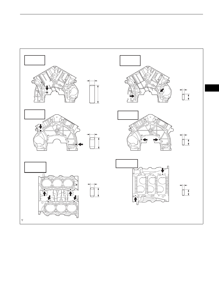
Pin B:
10.5 to 11.5 mm (0.413 to 0.453 in.)
Pin C:
8.5 to 9.5 mm (0.335 to 0.374 in.)
Pin D:
5.5 to 6.5 mm (0.217 to 0.256 in.)
4.
INSTALL TIGHT PLUG
(a) Apply adhesive around new tight plugs.
Adhesive:
Toyota Genuine Adhesive 1324, Three Bond
1324 or the equivalent
(b) Using SST, install the tight plugs as shown in the
illustration.
SST
09550-60010 (09951-00350), 09950-70010
(09951-07150)
10 mm
10 mm
8mm
36mm
22 mm
18mm
12 mm
12 mm
12 mm
Protrusion Height: 22.5 to 23.5 mm
Protrusion Height: 5.5 to 6.5 mm
Protrusion Height: 5.5 to 6.5 mm
Protrusion Height: 5.5 to 6.5 mm
Protrusion Height: 10.5 to 11.5 mm
Protrusion Height:
8.5 to 9.5 mm
D
D
D
4 mm
4 mm
4 mm
C
C
C
C
B
B
A
Front Side
Rear Side
Upper Side
Front Side
Rear Side
Lower Side
D
D
A076062E04