Toyota FJ Cruiser (GSJ 10, 15 series). Instruction - part 160


  Index      Toyota     Toyota FJ Cruiser (model GSJ 10, 15 series) - service repair instruction 2007 year


Search            copyright infringement  


Content   ..  158  159  160  161   ..


Toyota FJ Cruiser (GSJ 10, 15 series). Instruction - part 160


1GR-FE ENGINE MECHANICAL  –  CYLINDER HEAD

EM–73

EM

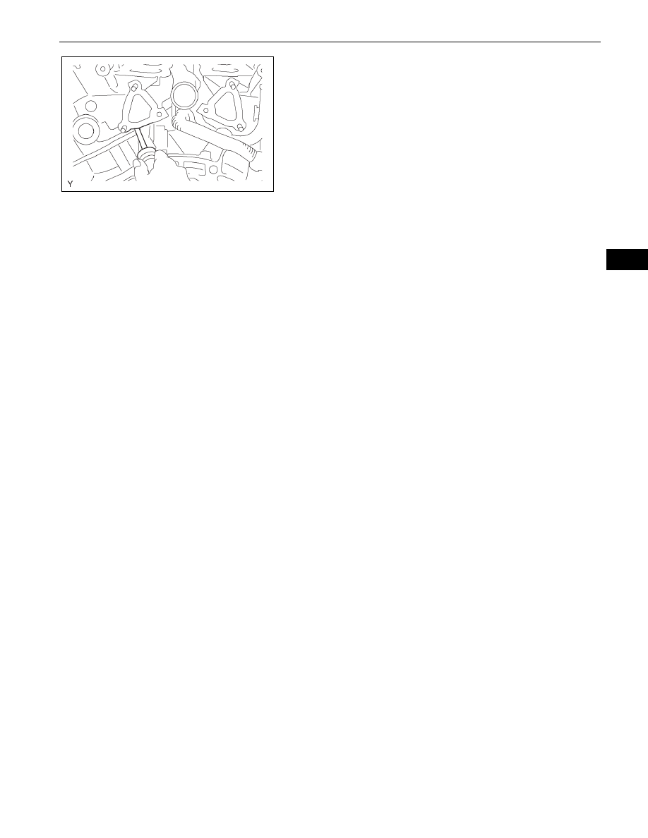
(e) Lift the cylinder head from the dowels on the 

cylinder block, and place the cylinder head on 
wooden blocks on a bench.
NOTICE:
Be careful not to drop the plate washers into the 
cylinder head.
If the cylinder head is difficult to remove, pry 
between the cylinder head and cylinder block with a 
screwdriver.

26. REMOVE NO. 2 CYLINDER HEAD GASKET

A076804E01

EM–74

1GR-FE ENGINE MECHANICAL  –  CYLINDER HEAD

EM

DISASSEMBLY

HINT:

Thoroughly clean all parts to be assembled.

Before installing the parts, apply new engine oil to all 
sliding and rotating surfaces.

Replace all gaskets, O-rings and oil seals with new parts.

1.

REMOVE VALVE LIFTER
HINT:
Arrange the valve lifter in the correct order.

2.

REMOVE VALVE
HINT:
Arrange the valves, inner compression springs, valve 
spring retainers and valve spring retainer locks in the 
correct order.
(a) Place the cylinder head on a wooden block.
(b) Using SST, compress the inner compression spring 

and remove the 2 valve spring retainer locks.
SST

09202-70020 (09202-00010)

(c) Remove the valve, inner compression spring and 

valve spring retainer.

3.

REMOVE VALVE SPRING SEAT
(a) Using compressed air and a magnetic finger, 

remove the valve spring seat by applying 
compressed air.

4.

REMOVE VALVE STEM OIL O SEAL OR RING
(a) Using needle-nose pliers, remove the valve stem oil 

seal.

5.

REMOVE STRAIGHT PIN NO.1
(a) Remove the 10 knock pins from bank 1 and bank 2 

cylinder heads.

A075601E01

SST

A075602E03

A075603E01

A075604E01

1GR-FE ENGINE MECHANICAL  –  CYLINDER HEAD

EM–75

EM

6.

REMOVE EXHAUST MANIFOLD, RH STUD BOLT
(a) Remove the 20 stud bolts from bank 1 and bank 2 

cylinder heads.

7.

REMOVE UNION
(a) Remove the 2 unions from bank 1 and bank 2 

cylinder heads.

Bank 1:

Bank 2:

Exhaust Side

Upper Side

Rear Side

Exhaust Side

Upper Side

Rear Side

A126358E01

Bank 1: Front Side

Bank 2: Intake Side

A126360E01

EM–76

1GR-FE ENGINE MECHANICAL  –  CYLINDER HEAD

EM

8.

REMOVE TIGHT PLUG
(a) Remove the 2 tight plugs from bank 1 and bank 2 

cylinder heads.

INSPECTION

1.

INSPECT CYLINDER HEAD SET BOLT
(a) Using vernier calipers, measure the outer diameter 

of the cylinder head set bolt thread.
Standard outer diameter:

10.85 to 11.00 mm (0.4272 to 0.4331 in.)

Minimum outer diameter:

10.7 mm (0.421 in.)

If the outer diameter is less than the minimum, 
replace the cylinder head set bolt.

2.

CLEAN CYLINDER HEAD SUB-ASSEMBLY
(a) Using a gasket scraper, remove all the gasket 

material from the cylinder block contact surface.
NOTICE:
Be careful not to scratch the cylinder block 
contact surface.

(b) Using a wire brush, remove all the carbon from the 

combustion chambers.
NOTICE:
Be careful not to scratch the combustion 
chambers.

Bank 1:

Bank 2:

A126362E01

A076820E01

A075605E01

A075606E01


Content   ..  158  159  160  161   ..