Toyota FJ Cruiser (GSJ 10, 15 series). Instruction - part 153


  Index      Toyota     Toyota FJ Cruiser (model GSJ 10, 15 series) - service repair instruction 2007 year


Search            copyright infringement  


Content   ..  151  152  153  154   ..


Toyota FJ Cruiser (GSJ 10, 15 series). Instruction - part 153


1GR-FE ENGINE MECHANICAL  –  CAMSHAFT

EM–45

EM

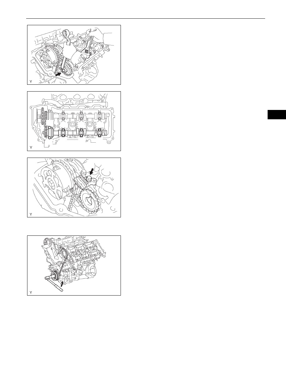
(b) Hold the hexagonal portion of the No. 4 camshaft 

with a wrench, and remove the camshaft timing gear 
set bolt.
NOTICE:
Be careful not to damage the cylinder head or 
valve lifter with the wrench.

(c) Separate the camshaft timing gear from the No. 4 

camshaft.

(d) Using several steps, uniformly loosen and remove 

the 8 bearing cap bolts in the sequence shown in 
the illustration.

(e) Remove the 4 bearing caps and No. 4 camshaft.

19. REMOVE NO. 3 CHAIN TENSIONER ASSEMBLY

(a) Remove the No. 3 chain tensioner bolt, then remove 

the No. 3 chain tensioner and camshaft timing gear.

20. REMOVE NO. 3 CAMSHAFT SUB-ASSEMBLY

NOTICE:
Keep the camshaft level while it is being removed. 
The camshaft thrust clearance is very small and 
failing to keep it level could crack or damage the 
cylinder head journal surface, which receives the 
thrust force. This could subsequently lead the 
camshaft to seize or break. Perform the following 
steps to avoid such problems.

(a) Release the chain tension between the camshaft 

timing gear (bank 2) and crankshaft timing gear by 
turning the crankshaft pulley counterclockwise 
slightly.

G036261E01

1

2

3

4

5

7

6

8

A076482E04

G036262E02

Slightly Turn 

G036263E01

EM–46

1GR-FE ENGINE MECHANICAL  –  CAMSHAFT

EM

(b) Hold the hexagonal portion of the No. 3 camshaft 

with a wrench, then loosen the camshaft timing gear 
set bolt.
NOTICE:

Be careful not to damage the cylinder head or 
valve lifter with the wrench.

Do not disassemble the camshaft timing gear 
assembly.

(c) Slide the camshaft timing gear and separate the No. 

1 chain from the camshaft timing gear.

(d) Using several steps, uniformly loosen and remove 

the 8 bearing cap bolts in the sequence shown in 
the illustration.

(e) Remove the 4 bearing caps.

(f)

Remove the camshaft timing gear set bolt with the 
No. 3 camshaft lifted up, then remove the No. 3 
camshaft and camshaft timing gear with No. 2 
chain.

(g) Tie the No. 1 chain with a piece of string as shown 

in the illustration.
NOTICE:
Be careful not to drop anything inside the timing 
chain cover.

G036264E01

Slide

G036265E01

1

2

4

6

7

3

5

8

A076487E04

G036266E01

A076489E01

1GR-FE ENGINE MECHANICAL  –  CAMSHAFT

EM–47

EM

INSPECTION

1.

INSPECT CAMSHAFTS
(a) Inspect the camshaft for runout.

(1) Place the camshaft on V-blocks.
(2) Using a dial indicator, measure the circle runout 

at the center journal.
Maximum runout:

0.06 mm (0.0024 in.)

If the circle runout is greater than the 
maximum, replace the camshaft.

(b) Inspect the cam lobes.

(1) Using a micrometer, measure the cam lobe 

height.
Standard cam lobe height:

Intake:

44.168 to 44.268 mm (1.7389 to 1.7428 
in.)

Exhaust:

44.580 to 44.680 mm (1.7551 to 1.7591 
in.)

Minimum cam lobe height:

Intake:

44.018 mm (1.7330 in.)

Exhaust:

44.430 mm (1.7492 in.)

If the cam lobe height is less than the minimum, 
replace the camshaft.

(c) Inspect the camshaft journals.

(1) Using a micrometer, measure the journal 

diameter.
No. 1 journal diameter:

35.971 to 35.985 mm (1.4162 to 1.4167 in.)

Other journal diameters:

22.959 to 22.975 mm (0.9039 to 0.9045 in.)

If the journal diameter is not as specified, check 
the oil clearance.

2.

INSPECT CAMSHAFT TIMING GEAR ASSEMBLY
(a) Fix the intake camshaft in a vise.

NOTICE:
Be careful not to damage the camshaft.

A005912E01

EM02011E01

No. 1 journal

RH
EX

RH
IN

LH
IN

LH
EX

No. 1 journal

No. 1 journal

No. 1 journal

A076249E03

EM–48

1GR-FE ENGINE MECHANICAL  –  CAMSHAFT

EM

(b) Align the knock pin hole in the camshaft timing gear 

assembly with the knock pin of the camshaft, and 
install the camshaft timing gear assembly with the 
bolt.
Torque: 100 N*m (1,020 kgf*cm, 74 ft.*lbf)

(c) Confirm that the camshaft timing gear assembly is 

locked.

(d) Release that lock pin.

(1) Cover the 4 oil paths of the cam journal with 

masking tape as shown in the illustration.
HINT:
One of the 2 grooves on the cam journal is for 
the retard side path (upper) and the other is for 
the advance side path (lower). Each groove 
has 2 oil paths. Plug one of the oil paths for 
each groove with a piece of rubber before 
wrapping the cam journal with tape.

(2) Puncture the tape covering the advance oil 

path and retard oil path on the opposite side of 
the groove as shown in the illustration.

(3) Apply compressed air at 200 kPa (2.0 kgf/cm

2

into the 2 broken paths (the advance side path 
and the retard side path).
NOTICE:
Cover the paths with a shop rag or piece of 
cloth to avoid oil splashes.

(4) Confirm that the camshaft timing gear 

assembly rotates in the timing advance 
direction when reducing the compressed air on 
the timing retard path.
HINT:
When the lock pin is released, the camshaft 
timing gear rotates in the advance direction.

Knock Pin

A076250E02

Retard Side 
Paths

Advance 
Side Paths

Closed

Closed

Open

Open

Rubber Piece

Masking Tape

G036837E04

Advanced 
Side Path

Retard 
Side Path

G036838E03

Advanced 
Side Path

Retard 
Side Path

Decompress

Hold pressure

G036839E02


Content   ..  151  152  153  154   ..