Toyota FJ Cruiser (GSJ 10, 15 series). Instruction - part 95
 

  Index      Toyota     Toyota FJ Cruiser (model GSJ 10, 15 series) - service repair instruction 2007 year


Search            copyright infringement  


Content   ..  93  94  95  96   ..


Toyota FJ Cruiser (GSJ 10, 15 series). Instruction - part 95


1GR-FE ENGINE CONTROL SYSTEM  –  SFI SYSTEM

ES–335

ES

*

 If only a small amount of fuel is in the fuel tank, it takes longer for the EVAP pressure to stabilize.

A

Atmospheric pressure 
measurement

Vent valve turned OFF (vent) and EVAP system pressure measured by ECM in order to 
register atmospheric pressure.
If pressure in EVAP system not between 70 kPa-a and 110 kPa-a (525 mmHg-a and 825 
mmHg-a), ECM cancels EVAP system monitor.

10 seconds

B

First reference 
pressure measurement

In order to determine reference pressure, leak detection pump creates negative pressure 
(vacuum) through reference orifice and then ECM checks if leak detection pump and vent 
valve operate normally.

60 seconds

C

EVAP system pressure 
measurement

Vent valve turned ON (closed) to shut EVAP system.
Negative pressure (vacuum) created in EVAP system, and EVAP system pressure then 
measured.
Write down measured value as will be used in leak check.
If EVAP pressure does not stabilize within 15 minutes, ECM cancels EVAP system monitor.

15 minutes

*

D

Purge VSV monitor

Purge VSV opened and then EVAP system pressure measured by ECM.
Large increase indicates normality.

10 seconds

E

Second reference 
pressure measurement

After second reference pressure measurement, leak check performed by comparing first and 
second reference pressure.
If stabilized system pressure higher than second reference pressure, ECM determines that 
EVAP system leaking.

60 seconds

F

Final check

Atmospheric pressure measured and then monitoring result recorded by ECM.

-

Sequ

ence

Operations

Descriptions

Duration

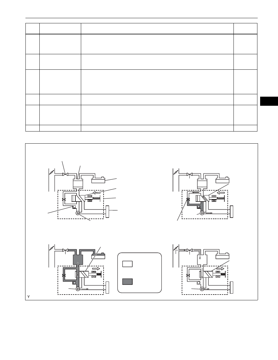
Operation A: Atmospheric Pressure Measurement

Operation C: EVAP System Pressure Measurement

Operation B, E:

Reference Pressure Measurement

Operation D: Purge VSV Monitor

Purge VSV: OFF

Canister

Fuel Tank

Vent Valve: OFF (vent)

Canister Pump Module

Canister Filter

Canister 
Pressure 
Sensor

Leak Detection Pump: OFF

OFF

ON

ON (closed)

Atmospheric 
Pressure

Negative 
Pressure

OFF

OFF (vent)

ON

Reference Orifice (0.02 Inch)

ON

ON

ON (closed)

A112612E01

ES–336

1GR-FE ENGINE CONTROL SYSTEM  –  SFI SYSTEM

ES

1. P2401: Leak detection pump stuck OFF

In operation B, the leak detection pump creates negative pressure (a vacuum) through the reference 
orifice. The EVAP system pressure is then measured by the ECM, using the canister pressure sensor, 
to determine the reference pressure. If the pressure is higher than -1.057 kPa-g (-7.93 mmHg-g), or 
lower than -4.85 kPa-g (-36.4 mmHg-g), the ECM interprets this as the leak detection pump being 
stuck OFF (not operating). The ECM illuminates the MIL and sets the DTC (2 trip detection logic).

EVAP Pressure when Leak Detection Pump Stuck OFF:

Leak Detection  
Pump

Purge VSV

Vent Valve

EVAP Pressure

Positive

Negative

Sequence

Time

First Reference  
Pressure

10 seconds

60 
seconds

60 
seconds

10 
seconds

ON: Open

OFF: Closed

ON: Closed

OFF: Vent

Malfunction

OK

ON

ON

ON

A

B

C

D

E

Within 15 minutes

A106064E05

1GR-FE ENGINE CONTROL SYSTEM  –  SFI SYSTEM

ES–337

ES

2. P2402: Leak detection pump stuck ON

In operation B, the leak detection pump creates negative pressure (a vacuum) through the reference 
orifice. The EVAP (Evaporative Emission) system pressure is then measured by the ECM, using the 
canister pressure sensor, to determine the reference pressure. If the pressure is higher than -1.057 
kPa-g (-7.93 mmHg-g), or lower than -4.85 kPa-g (-36.4 mmHg-g), the ECM interprets this as the leak 
detection pump being stuck ON (remaining ON all the time). The ECM illuminates the MIL and sets the 
DTC (2 trip detection logic).

HINT:
The detection logic of DTCs P2401 and P2402 is the same because in both cases the reference 
pressure measured in operation B is compared to the atmospheric pressure registered in operation A. 
The ECM calculates the difference between these pressures by deducting [the reference pressure] 
from [the stored atmospheric pressure], and uses this to monitor the EVAP system pressure change.

MONITOR STRATEGY

TYPICAL ENABLING CONDITIONS

Required Sensors/Components

Purge VSV and canister pump module

Frequency of Operation

Once per driving cycle

Duration

Within 2 minutes (varies with amount of fuel in tank)

MIL Operation

2 driving cycles

Sequence of Operation

None

Monitor runs whenever following DTCs not present

None

EVAP key-off monitor runs when all of following conditions met

-

Atmospheric pressure

70 to 110 kPa-a (525 to 825 mmHg-a)

Battery voltage

10.5 V or more

EVAP Pressure when Leak Detection Pump Stuck ON:

Purge VSV

Vent Valve

Leak Detection  
Pump

EVAP Pressure

Positive

Negative

First Reference  
Pressure

Sequence

10 seconds

60 
seconds

60 
seconds

10 
seconds

Malfunction

OK

ON

ON

ON

C

A

B

D

E

Time

ON: Open

OFF: Closed
ON: Closed

OFF: Vent

Within 15 minutes

A106065E04

ES–338

1GR-FE ENGINE CONTROL SYSTEM  –  SFI SYSTEM

ES

1.

Key-off monitor sequence 1 to 8

1. Atmospheric pressure measurement

2. First reference pressure measurement

3. Vent valve stuck closed check

4. Vacuum introduction

5. Purge VSV stuck closed check

6. Second reference pressure measurement

7. Leak check 

8. Atmospheric pressure measurement

Vehicle speed

Below 2.5 mph (4 km/h)

Ignition switch

OFF

Time after key off

5 or 7 or 9.5 hours

Canister pressure sensor malfunction (P0450, P0451, P0452 and 
P0453)

Not detected

Purge VSV

Not operated by scan tool

Vent valve

Not operated by scan tool

Leak detection pump

Not operated by scan tool

Both of following conditions met before key off

Conditions 1 and 2

1. Duration that vehicle driven

5 minutes or more

2. EVAP purge operation

Performed

ECT

4.4

° to 35°C (40° to 95°F)

IAT

4.4

°to 35°C (40° to 95°F)

Next sequence run if following condition set

-

Atmospheric pressure change

Less than 0.3 kPa-g (2.25 mmHg-g) in 1 second

Next sequence run if all of following conditions set

Condition 1, 2 and 3

1. EVAP pressure just after reference pressure measurement start

-1 kPa-g (-7.5 mmHg-g) or less

2. Reference pressure

-4.85 to -1.057 kPa-g (-36.4 to -7.93 mmHg-g)

3. Reference pressure

Saturated within 60 seconds

Next sequence run if following condition set

-

EVAP pressure change after vent valve ON (closed)

0.3 kPa-g (2.25 mmHg-g) or more

Next sequence run if following condition set

-

EVAP pressure

Saturated within 15 minutes

Next sequence run if following condition set

-

EVAP pressure change after purge VSV ON (open)

0.3 kPa-g (2.25 mmHg-g) or more

Next sequence run if all of following conditions set

Condition 1, 2, 3 and 4

1. EVAP pressure just after reference pressure

-1 kPa-g (-7.5 mmHg-g) or less

2. Reference pressure

-4.85 to -1.057 kPa-g (-36.4 to -7.93 mmHg-g)

3. Reference pressure

Saturated within 60 seconds

4. Reference pressure difference between first and second

Less than 0.7 kPa-g (5.25 mmHg-g)

Next sequence run if following condition set

-

EVAP pressure when vacuum introduction complete

Second reference pressure or less

EVAP monitor complete if following condition set

-

Atmospheric pressure difference between sequence 1 and 8

Within 0.3 kPa-g (2.25 mmHg-g)


Content   ..  93  94  95  96   ..