Toyota FJ Cruiser (GSJ 10, 15 series). Instruction - part 92
1GR-FE ENGINE CONTROL SYSTEM – SFI SYSTEM
ES–323
ES
•
The ECM stops fuel injection (fuel cut) during engine
deceleration. This causes a lean condition and results in a
momentary increase in the A/F sensor output voltage.
•
The ECM must establish a closed throttle valve position
learning value to perform fuel cut. If the battery terminal
has been reconnected, the vehicle must be driven over 10
mph (16 km/h) to allow the ECM to learn the closed throttle
valve position.
•
When the vehicle is driven:
The output voltage of the A/F sensor may be below 2.8 V
during fuel enrichment. For the vehicle, this translates to a
sudden increase in speed with the accelerator pedal fully
depressed when trying to overtake another vehicle. The A/
F sensor is functioning normally.
•
The A/F sensor is a current output element; therefore, the
current is converted into a voltage inside the ECM.
Measuring the voltage at the connectors of the A/F sensor
or ECM will show a constant voltage result.
NG
OK
NEXT
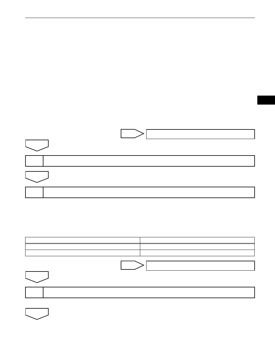
(a) Connect an intelligent tester to the DLC3.
(b) Turn the ignition switch ON and the tester ON.
(c) Select the following menu items: DIAGNOSIS /
ENHANCED OBD II / DTC INFO / PENDING CODES.
(d) Read DTCs.
Result
B
A
Replace the air fuel ratio sensor (See page
NEXT
Go to step 10
4
PERFORM CONFIRMATION DRIVING PATTERN
5
CHECK WHETHER DTC OUTPUT RECURS (DTC P2195, P2196, P2197 OR P2198)
Display (DTC Output)
Proceed To
P2195, P2196, P2197 or P2198
A
No output
B
Go to step 9
6
REPLACE AIR FUEL RATIO SENSOR