Toyota FJ Cruiser (GSJ 10, 15 series). Instruction - part 56


  Index      Toyota     Toyota FJ Cruiser (model GSJ 10, 15 series) - service repair instruction 2007 year


Search            copyright infringement  


Content   ..  54  55  56  57   ..


Toyota FJ Cruiser (GSJ 10, 15 series). Instruction - part 56


1GR-FE ENGINE CONTROL SYSTEM  –  SFI SYSTEM

ES–179

ES

(a) Connect an intelligent tester to the DLC3.
(b) Turn the ignition switch ON.
(c) Turn the tester ON.
(d) Select the following menu items: DIAGNOSIS / 

ENHANCED OBD II / DTC INFO / CURRENT CODES.

(e) Read DTCs.

Result

HINT:
If any DTCs other than P0300, P0301, P0302, P0303, 
P0304, P0305 and P0306 are output, troubleshoot those 
DTCs first.

B

A

(a) Connect an intelligent tester to the DLC3.
(b) Turn the ignition switch ON and turn the tester ON.
(c) Select the following menu items: DIAGNOSIS / 

ENHANCED OBD II / DATA LIST / MISFIRE / MISFIRE 
RPM and MISFIRE LOAD.

(d) Read and note the MISFIRE RPM and MISFIRE LOAD 

(engine load) values.
HINT:
The MISFIRE RPM and MISFIRE LOAD indicate the 
vehicle conditions under which the misfire occurred.

NEXT

OK:

PCV hose is connected correctly and is not damaged.

NG

OK

(a) Connect an intelligent tester to the DLC3.
(b) Turn the ignition switch ON.
(c) Turn the tester ON.
(d) Clear DTCs (See page 

ES-38

).

1

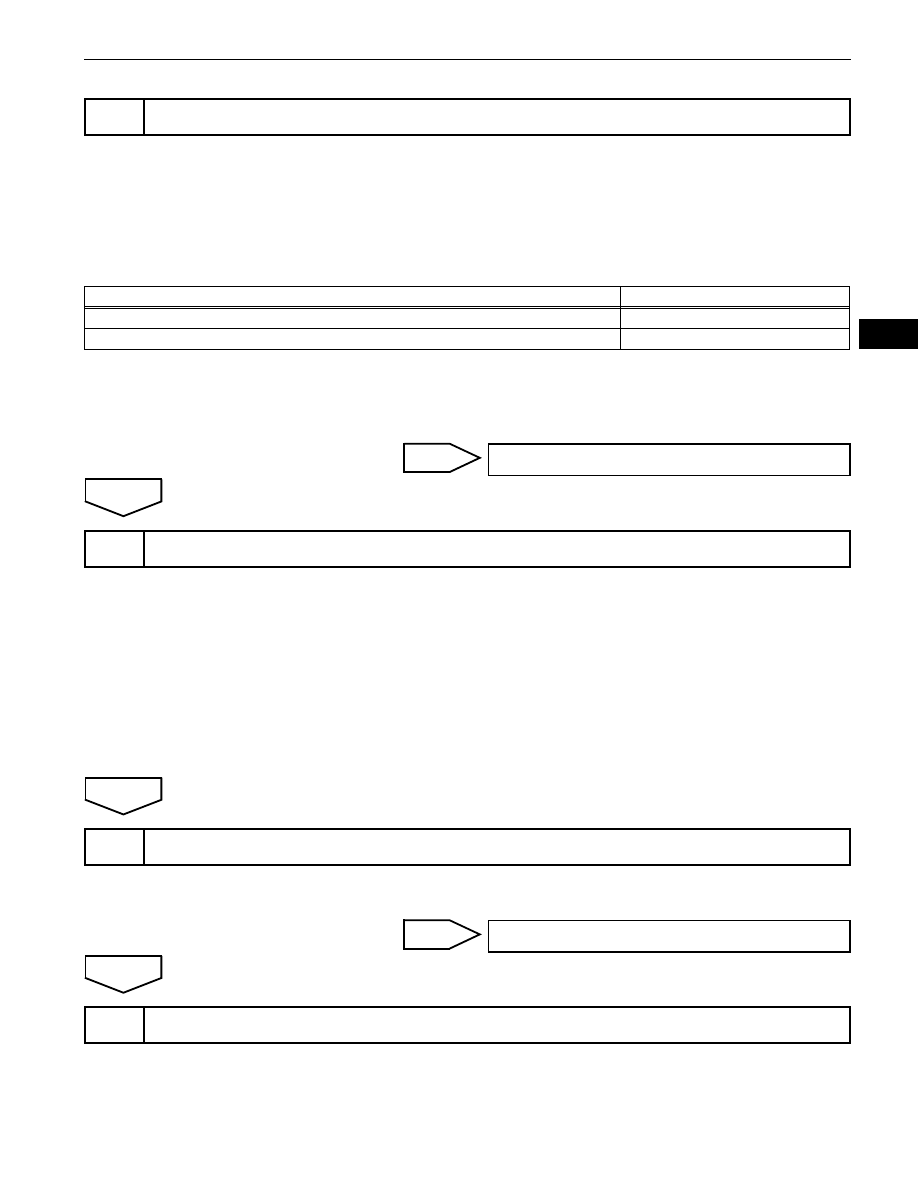
CHECK ANY OTHER DTCS OUTPUT (IN ADDITION TO MISFIRE DTCS)

Display (DTC Output)

Proceed To

P0300, P0301, P0302, P0303, P0304, P0305 and/or P0306

A

P0300, P0301, P0302, P0303, P0304, P0305 and/or P0306 and other DTCs

B

GO TO DTC CHART (See page 

ES-57

)

2

READ VALUE USING INTELLIGENT TESTER (MISFIRE RPM AND MISFIRE LOAD)

3

CHECK PCV HOSE CONNECTIONS

REPAIR OR REPLACE PCV HOSE

4

CHECK MISFIRE COUNT (CYL #1, #2, #3, #4, #5 AND #6)

ES–180

1GR-FE ENGINE CONTROL SYSTEM  –  SFI SYSTEM

ES

(e) Select the following menu items: DIAGNOSIS / 

ENHANCED OBD II / DATA LIST / MISFIRE / CYL #1, 
#2, #3, #4, #5 and #6.

(f)

Allow the engine to idle.

(g) Read each value of CYL #1 to #6 displayed on the tester. 

If no misfire counts occur in any cylinders, perform the 
following operations:
(1) Shift the gear selector lever to the D position.
(2) Repeat steps (e) to (g) above.
(3) Check the CYL #1 to #6.
(4) If misfire counts are still not displayed, perform 

steps (h) and (i) and then check the misfire counts 
again.

(h) Drive the vehicle with the MISFIRE RPM and MISFIRE 

LOAD noted in step 2.

(i)

Read the CYL #1 to #6 or DTCs displayed on the tester.

Result

B

A

(a) Remove the ignition coil and the spark plug of the 

misfiring cylinder.

(b) Measure the spark plug electrode gap.

Standard:

1.0 to 1.1 mm (0.039 to 0.043 in.)

(c) Check the electrode for carbon deposits.

Recommended spark plug

NOTICE:
If the electrode gap is larger than standard, replace 
the spark plug. Do not adjust the electrode gap.

(d) Reinstall the ignition coil and the spark plug.

NG

OK

(a) Disconnect the injector connectors, in order to prevent 

the engine from starting.

(b) Install the spark plug to the ignition coil.

Misfire Count

Proceed To

One or two cylinders have misfire counts

A

Three cylinders or more have misfire counts

B

              Go to step 13

5

CHECK SPARK PLUG

Electrode Gap

A088861E07

Manufactures

Products

DENSO

K20HR-U11

NGK

LFR6C11

REPLACE SPARK PLUG

6

CHECK SPARKS AND IGNITION

1GR-FE ENGINE CONTROL SYSTEM  –  SFI SYSTEM

ES–181

ES

(c) Attach the spark plug assembly to the cylinder head 

cover.

(d) Crank the engine for less than 2 seconds and check the 

spark.
OK:

Sparks jump across electrode gap

(e) Reconnect the injector connectors.

NG

OK

(a) Measure the cylinder compression pressure of the 

misfiring cylinder.

OK

NG

(a) Change the installed spark plug to a spark plug that 

functions normally.

(b) Perform a spark test.

CAUTION:
Always disconnect each injector connector.
NOTICE:
Do not crank the engine for more than 2 seconds.
(1) Install the spark plug to the ignition coil and connect 

the ignition coil connector.

(2) Disconnect the injector connector.
(3) Ground the spark plug.
(4) Check if sparks occur while the engine is being 

cranked.
OK:

Sparks jump across electrode gap.

NG

OK

              Go to step 8

7

CHECK CYLINDER COMPRESSION PRESSURE OF MISFIRING CYLINDER

              Go to step 9

REPAIR OR REPLACE MALFUNCTION PARTS

8

CHANGE NORMAL SPARK PLUG AND CHECK SPARK OF MISFIRING CYLINDER

REPLACE IGNITION COIL ASSEMBLY THEN 
CONFIRM THAT THERE IS NO MISFIRE

REPLACE SPARK PLUG

ES–182

1GR-FE ENGINE CONTROL SYSTEM  –  SFI SYSTEM

ES

(a) Turn the ignition switch ON.
(b) Measure the voltage between the terminals of the B1 

and B3 ECM connectors.
Standard Voltage

OK

NG

(a) Disconnect the injector connector (of the misfiring 

cylinder).

(b) Disconnect the B3 ECM connector.
(c) Turn the ignition switch ON.
(d) Measure the resistance and voltage between the injector 

and the ECM connector terminals.
Standard (Cylinder No. 1)

Standard (Cylinder No. 2)

Standard (Cylinder No. 3)

Standard (Cylinder No. 4)

9

INSPECT ECM TERMINAL VOLTAGE OF MISFIRING CYLINDER (#10, #20, #30, #40, #50 
AND/OR #60 VOLTAGE)

#60 (+)

ECM Connector

B1

B3

E01 (-)

#50 (+)

#40 (+)

#30 (+)

#20 (+)

#10 (+)

A115970E10

Tester Connections

Specified Conditions

#10 (B3-2) - E01 (B1-7)

11 to 14 V

#20 (B3-3) - E01 (B1-7)

#30 (B3-4) - E01 (B1-7)

#40 (B3-5) - E01 (B1-7)

#50 (B3-6) - E01 (B1-7)

#60 (B3-7) - E01 (B1-7)

              Go to step 11

10

CHECK HARNESS AND CONNECTOR (INJECTOR - ECM)

B3

Wire Harness Side:

ECM Connector

Front View

Injector 
Connector

#10
#20
#30

#60

#50
#40

B25

B9

B11

B21

B10

B18

A116171E03

Tester Connections

Specified Conditions

B11-2 - Ground

11 to 14 V

B11-1 - Ground

10 k

 or higher

B11-1 - #10 (B3-2)

Below 1 

Tester Connections

Specified Conditions

B25-2 - Ground

11 to 14 V

B25-1 - Ground

10 k

 or higher

B25-1 - #20 (B3-3)

Below 1 

Tester Connections

Specified Conditions

B10-2 - Ground

11 to 14 V

B10-1 - Ground

10 k

 or higher

B10-1 - #30 (B3-4)

Below 1 

Tester Connections

Specified Conditions

B21-2 - Ground

11 to 14 V

B21-1 - Ground

10 k

 or higher


Content   ..  54  55  56  57   ..