Toyota FJ Cruiser (GSJ 10, 15 series). Instruction - part 33


  Index      Toyota     Toyota FJ Cruiser (model GSJ 10, 15 series) - service repair instruction 2007 year


Search            copyright infringement  


Content   ..  31  32  33  34   ..


Toyota FJ Cruiser (GSJ 10, 15 series). Instruction - part 33


1GR-FE ENGINE CONTROL SYSTEM  –  SFI SYSTEM

ES–87

ES

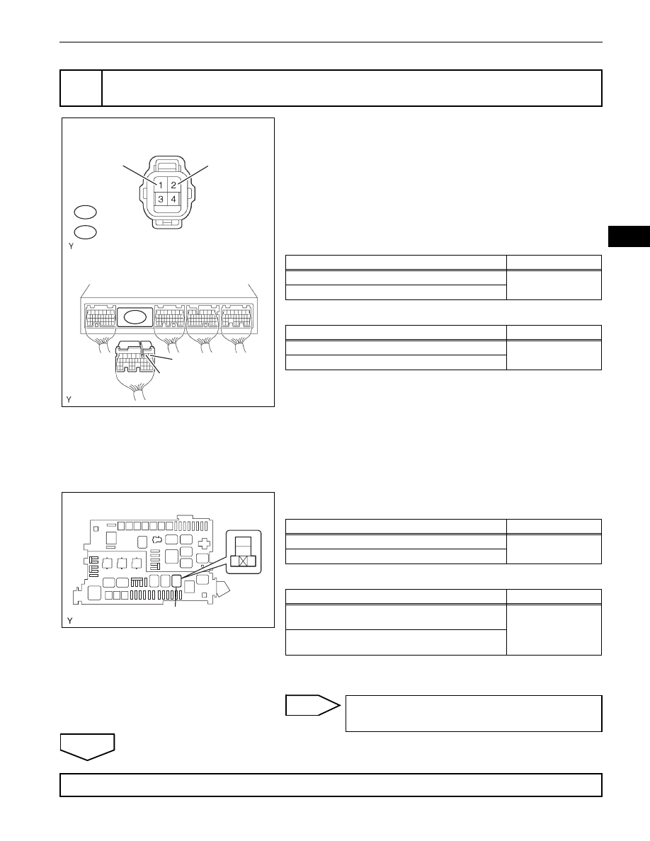
(a) Check the harness and the connector between the ECM 

and the A/F sensor.
(1) Disconnect the B33*1 or B31*2 A/F sensor 

connector.
HINT:

*1: Bank 1 Sensor 1

*2: Bank 2 Sensor 1

(2) Disconnect the B2 ECM connector.
(3) Check the resistance.

Standard Resistance (Check for open)

Standard Resistance (Check for short)

(4) Reconnect the A/F sensor connector.
(5) Reconnect the ECM connector.

(b) Check the harness and the connector between the A/F 

sensor and A/F sensor heater relay.
(1) Disconnect the B33*1 or B31*2 A/F sensor 

connector.

(2) Remove the A/F sensor heater relay from the 

engine room relay block.

(3) Check the resistance.

Standard Resistance (Check for open)

Standard Resistance (Check for short)

(4) Reconnect the A/F sensor connector.
(5) Reinstall the A/F sensor heater relay.

NG

OK

4

CHECK HARNESS AND CONNECTOR (A/F SENSOR - ECM, A/F SENSOR - A/F SENSOR 
HEATER RELAY)

B31

Wire Harness Side:

A/F Sensor 
Connector

B33 *1

*2

Front View

+B

HA1A *1 
HA2A *2

*1: Bank 1 
*2: Bank 2

B2

ECM Connector

HA2A

HA1A

A116153E09

Tester Connections

Specified Conditions

HA1A (B33-1) - HA1A (B2-2)

Below 1 

HA2A (B31-1) - HA2A (B2-1)

Tester Connections

Specified Conditions

HA1A (B33-1) or HA1A (B2-2) - Body ground

10 k

 or higher

HA2A (B31-1) or HA2A (B2-1) - Body ground

1

2

5

3

A/F Sensor Heater Relay

Engine Room Relay Block

A133433E01

Tester Connections

Specified Conditions

+B (B33-2) - A/F sensor heater relay (3)

Below 1 

+B (B31-2) - A/F sensor heater relay (3)

Tester Connections

Specified Conditions

+B (B33-2) or A/F sensor heater relay (3) - Body 

ground

10 k

 or higher

+B (B31-2) or A/F sensor heater relay (3) - Body 

ground

REPAIR OR REPLACE HARNESS OR 
CONNECTOR

REPLACE ECM (See page 

ES-446

)

ES–88

1GR-FE ENGINE CONTROL SYSTEM  –  SFI SYSTEM

ES

HINT:
Sensor 2 refers to the sensor mounted behind the Three-Way Catalytic Converter (TWC) and located far 
from the engine assembly.

DESCRIPTION

Refer to DTC P0136 (See page 

ES-133

).

HINT:

When any of these DTCs are set, the ECM enters fail-safe mode. The ECM turns off the Heated 
Oxygen (HO2) Sensor heater in fail-safe mode. Fail-safe mode continues until the engine switch is 
turned off.

DTC

P0037

Oxygen Sensor Heater Control Circuit Low 
(Bank 1 Sensor 2)

DTC

P0038

Oxygen Sensor Heater Control Circuit High 
(Bank 1 Sensor 2)

DTC

P0057

Oxygen Sensor Heater Control Circuit Low 
(Bank 2 Sensor 2)

DTC

P0058

Oxygen Sensor Heater Control Circuit High 
(Bank 2 Sensor 2)

DTC

P0141

Oxygen Sensor Heater Circuit Malfunction 
(Bank 1 Sensor 2)

DTC

P0161

Oxygen Sensor Heater Circuit Malfunction 
(Bank 2 Sensor 2)

1GR-FE ENGINE CONTROL SYSTEM  –  SFI SYSTEM

ES–89

ES

The ECM provides a pulse width modulated control circuit to adjust the current through the heater. The 
HO2 sensor heater circuit uses a relay on the +B side of the circuit.

HINT:

Bank 1 refers to the bank that includes cylinder No. 1.

Bank 2 refers to the bank that does not include cylinder No. 1.

Sensor 1 refers to the sensor closest to the engine assembly.

Sensor 2 refers to the sensor farthest away from the engine assembly.

MONITOR DESCRIPTION

The sensing position of the Heated Oxygen (HO2) sensor has a zirconia element which is used to detect 
the oxygen concentration in the exhaust gas. If the zirconia element is at the appropriate temperature, 
and the difference between the oxygen concentrations surrounding the inside and outside surfaces of the 
sensor is large, the zirconia element generates voltage signals. In order to increase the oxygen 
concentration detecting capacity of the zirconia element, the ECM supplements the heat from the exhaust 
with heat from a heating element inside the sensor. 
Heated oxygen sensor heater range check (P0037, P0038, P0057 and P0058):
The ECM monitors the current applied to the O2 sensor heater to check the heater for malfunctions. If the 
current is below the threshold value, the ECM will determine that there is an open circuit in the heater. If 
the current is above the threshold value, the ECM will determine that there is a short circuit in the heater.

Example:

DTC No.

DTC Detection Conditions

Trouble Areas

P0037
P0057

Heated Oxygen (HO2) sensor heater current less than 0.3 A 
(1 trip detection logic)

Open in HO2 sensor heater circuit

HO2 sensor heater

EFI  relay

ECM

P0038
P0058

Heated Oxygen (HO2) sensor heater current more than 2 A 
(1 trip detection logic)

Short in HO2 sensor heater circuit

HO2 sensor heater

EFI  relay

ECM

P0141
P0161

Cumulative heater resistance correction value exceeds the 
acceptable threshold. (2 trip detection logic)

Open or short in HO2 sensor heater circuit

HO2 sensor heater

EFI  relay

ECM

Reference (System Diagram of Bank 1 Sensor 2):

From 
Battery

EFI

EFI

Ground

Heater

Sensor

HO2 Sensor

EFI NO. 2

OX1B

E2

MREL

HT1B

OX1B

HT1B

E2

+B

ECM

Duty 
Control

A103832E33

ES–90

1GR-FE ENGINE CONTROL SYSTEM  –  SFI SYSTEM

ES

The ECM sets DTC P0038 or P0058 when the current in the HO2 sensor heater is more than 2 A. 
Conversely, when the heater current is less than 0.3 A, DTC P0037 or P0057 is set.

Heated oxygen sensor heater performance (P0141 and P0161):
After the accumulated heater ON time exceeds 100 seconds, the ECM calculates the heater resistance 
using the battery voltage and the current applied to the heater. If the resistance is above the threshold 
value, the ECM will determine that there is a malfunction in the HO2S heater and set DTC P0141 and 
P0161.

MONITOR STRATEGY

TYPICAL ENABLING CONDITIONS

All:

P0037 and P0057:

P0038 and P0058 (Case 1):

P0038 and P0058 (Case 2):

P0141 and P0161:

Related DTCs

P0037: Heated oxygen sensor heater (bank 1 sensor 2) open/short 
(Low electrical current)
P0038: Heated oxygen sensor heater (bank 1 sensor 2) open/short 
(High electrical current)
P0057: Heated oxygen sensor heater (bank 2 sensor 2) open/short 
(Low electrical current)
P0058: Heated oxygen sensor heater (bank 2 sensor 2) open/short 
(High electrical current)
P0141: Heated oxygen sensor heater performance (bank 1 sensor 2)
P0161: Heated oxygen sensor heater performance (bank 2 sensor 2)

Required sensors / components (Main)

Heated oxygen sensor heater (bank 1 sensor 2)
Heated oxygen sensor heater (bank 2 sensor 2)

Required sensors / components (Sub)

-

Frequency of operation

Continuous: P0037, P0038, P0057, P0058
Once per driving cycle: P0141, P0161

Duration

0.5 seconds: P0037, P0057
Within 1 second: P0038, P0058
10 seconds: P0141 and P0161

MIL operation

Immediate: P0037, P0038, P0057 and P0058
2 driving cycles: P0141 and P0161

Sequence of operation

None

Monitor runs whenever following DTCs are not present

None

Battery voltage

10.5 to 20 V

Battery voltage

10.5 V or more

Engine

Running

Starter

OFF

Battery voltage

10.5 to 20 V

One of the following conditions is met:

Condition A or B

A. All of the following conditions are met:

Condition 1, 2, 3, 4 and 5

1. Battery voltage

10.5 V or more

2. Fuel cut

OFF

3. Time after fuel cut ON to OFF

30 seconds or more

4. Accumulated heater ON time

100 seconds or more

5. Learned heater OFF current operation

Completed

B. Duration that rear heated oxygen sensor impedance is less than 15 
k

2 seconds or more


Content   ..  31  32  33  34   ..