Toyota FJ Cruiser (GSJ 10, 15 series). Instruction - part 11


  Index      Toyota     Toyota FJ Cruiser (model GSJ 10, 15 series) - service repair instruction 2007 year


Search            copyright infringement  


Content   ..  9  10  11  12   ..


Toyota FJ Cruiser (GSJ 10, 15 series). Instruction - part 11


1GR-FE EMISSION CONTROL  –  HEATED OXYGEN SENSOR

EC–25

EC

INSTALLATION

1.

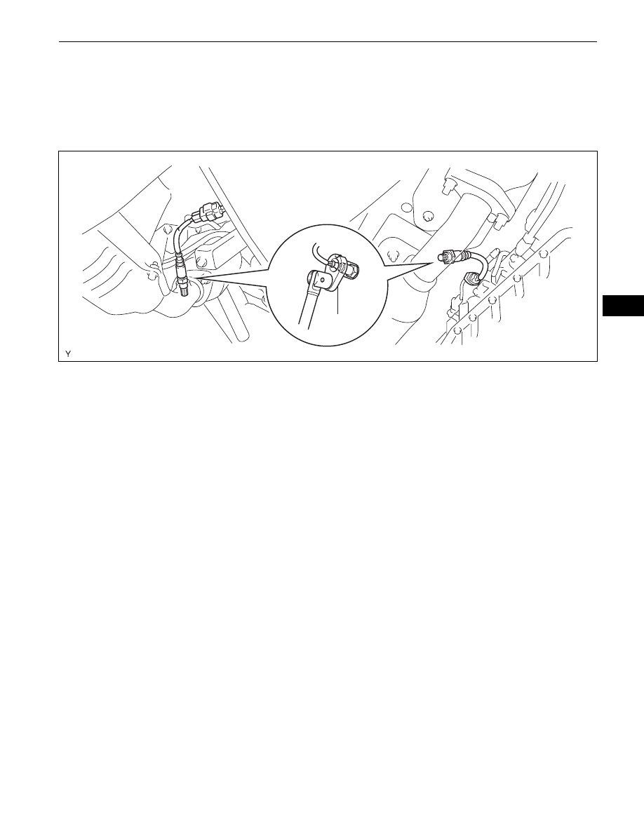
INSTALL HEATED OXYGEN SENSOR
(a) Using SST, install the 2 heated oxygen sensors onto 

the exhaust pipe.
SST

09224-00010

Torque: 44 N*m (449 kgf*cm, 33 ft.*lbf)

(b) Connect the 2 heated oxygen sensor connectors.

2.

CONNECT CABLE TO NEGATIVE BATTERY 
TERMINAL
Torque: 3.9 N*m (40 kgf*cm, 35 in.*lbf)

SST

For RH side:

For LH side:

A128844E01

EC–26

1GR-FE EMISSION CONTROL  –  FUEL TANK CAP

EC

FUEL TANK CAP

ON-VEHICLE INSPECTION

1.

INSPECT FUEL TANK CAP ASSEMBLY
(a) Check that there is no deformation or damage to 

fuel tank cap or gasket. If necessary replace the fuel 
tank cap.

Gasket

A117785E01

1GR-FE ENGINE CONTROL SYSTEM  –  SFI SYSTEM

ES–1

ES

SFI SYSTEM

PRECAUTION

1.

INITIALIZATION
NOTICE:

Perform the RESET MEMORY (AT initialization) 
when replacing the automatic transmission 
assembly, engine assembly or ECM (See page 

AT-

19

).

Perform the REGISTRATION (VIN registration) 
when replacing the ECM (See page 

ES-15

).

If the ECM has been replaced or RESET MEMORY 
(AT initialization) has been performed, set up the 
function of the ATF (Automatic Transmission 
Fluid) temperature warning light (See page 

AT-19

).

HINT:
Initialization can not be completed by only removing the 
battery.

2.

FOR USING INTELLIGENT TESTER
CAUTION:
Observe the following items for safety reasons:

Read its instruction books before using the tester.

Prevent the tester cable from being caught on the 
pedals, shift lever and steering wheel when driving 
with the tester connected to the vehicle.

When driving the vehicle for testing purposes using 
the tester, two persons are required. One is for driving 
the vehicle, and the other operates the tester.

3.

DISCONNECT AND RECONNECT CABLE OF 
NEGATIVE BATTERY TERMINAL
(a) Before performing electronic work, disconnect the 

cable from the negative (-) battery terminal in order 
to prevent it from shorting and burning out.

(b) Before disconnecting and reconnecting the battery 

cable, turn the ignition switch OFF and the headlight 
dimmer switch OFF. Then loosen the terminal nut 
completely. Do not damage the cable or terminal.

(c) When the battery cable is disconnected, the clock 

and radio settings and stored DTCs are erased. 
Therefore, before disconnecting the battery cable, 
make a notes of them.

NOTICE:
When the cable is disconnected from the negative (-) 
battery terminal, initialize the following system(s) after 
the cable is reconnected.

Negative (-) 
Battery Terminal

Cable

D033496E01

System name

See procedure

METER / GAUGE SYSTEM

ME-10

ES–2

1GR-FE ENGINE CONTROL SYSTEM  –  SFI SYSTEM

ES

DEFINITION OF TERMS

Terms

Definitions

Monitor Description

Description of what ECM monitors and how detects malfunctions (monitoring purpose and 
details)

Related DTCs

A group of diagnostic trouble codes that are output by ECM based on same malfunction 
detection logic.

Typical Enabling Conditions

Preconditions that allow ECM to detect malfunctions.
With all preconditions satisfied, ECM sets DTC when monitored value(s) exceeds malfunction 
threshold(s)

Sequence of Operation

Order of monitor priority, applied if multiple sensors and components involved in single 
malfunction detection process.
Each sensor and component monitored in turn and not monitored until previous detection 
operation completed.

Required Sensors/Components

Sensors and components used by ECM to detect each malfunction.

Frequency of Operation

Number of times ECM checks for each malfunction during each driving cycle.
"Once per driving cycle" means ECM only performs checks for that malfunction once during 
single driving cycle.
"Continuous" means ECM performs checks for that malfunction whenever enabling conditions 
met.

Duration

Minimum time for which ECM must detect continuous deviation in monitored value(s) in order to 
set DTC. Timing begins when Typical Enabling Conditions met.

Malfunction Thresholds

Values, beyond which, ECM determines malfunctions exist and sets DTCs.

MIL Operation

Timing of MIL illumination after defect detected.
"Immediate" means ECM illuminates MIL as soon as malfunction detected.
"2 driving cycles" means ECM illuminates MIL if same malfunction detected second time during 
next sequential driving cycle.


Content   ..  9  10  11  12   ..