Toyota Sequoia (2005). Manual - part 856


  Главная      Automobile - Toyota     Toyota Sequoia - Repair manual 2005 year


поиск по сайту           правообладателям


содержание   ..  854  855  856  857   ..


Toyota Sequoia (2005). Manual - part 856


BODY ELECTRICAL

TROUBLESHOOTING

BE–9

3413

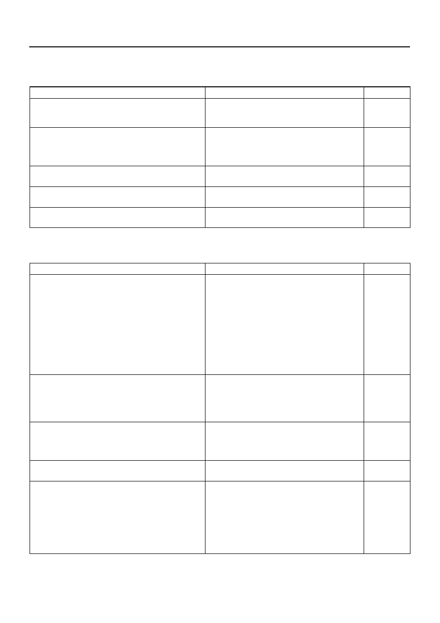
POWER DOOR LOCK CONTROL SYSTEM
This system uses the multiplex communication system, so check diagnosis system of the multiplex commu-
nication system before you proceed with troubleshooting.

Symptom

Suspect Area

See page

All the doors cannot be locked or unlocked.

(Power window control system is normal.)

1. Door Unlock Detection Switch

2. Door Key Lock and Unlock Switch

3. Driver Door ECU

BE–79

BE–79

Only one back lock control does not operate.

1. Back Door Lock Motor

2. Back Door Unlock Detection Switch

3. Back Door Key Lock and Unlock Switch

4. Back Door ECU

BE–79

BE–79

BE–79

Driver door key related function does not operate.

1. Door Key Lock and Unlock Switch

2. Driver Door ECU

BE–79

Front passenger door key related function does not operate.

1. Door Key Lock and Unlock Switch

2. Passenger Door ECU

BE–79

Back door key related function does not operate.

1. Door Key Lock and Unlock Switch

2. Back Door ECU

BE–79

THEFT DETERRENT SYSTEM
This system uses the multiplex communication system, so check diagnosis system of the multiplex commu-
nication system before you proceed with troubleshooting.

Symptom

Suspect Area

See page

The theft deterrent system cannot be set.

1. Key Unlock Warning Switch Circuit

2. Door Unlock Detection Switch Circuit (Driver Door ECU)

Door Unlock Detection Switch Circuit (Passenger Door

ECU)

Door Unlock Detection Switch Circuit (Back Door ECU)

Door Unlock Detection Switch Circuit (Body ECU)

3. Engine Hood Courtesy Switch Circuit

4. Back Door Courtesy Light Switch

5. Courtesy Light Switch Circuit

6. Glass Breakage Sensor Circuit (*1)

7. Body ECU

DI–1715

DI–1791

DI–1829

DI–1869

DI–1723

DI–1725

DI–1864

DI–1728

DI–1774

The system cannot be canceled when the ignition switch is turned

ON with a key.

1. AM1 Fuse

2. AM2 Fuse

3. Key Unlock Warning Switch Circuit

4. Ignition Switch

5. Body ECU

BE–14

BE–14

DI–1715

BE–24

The system cannot be canceled when the back door is unlocked

with a key.

1. Back Door Unlock Detection Switch Circuit

2. Back Door Key Lock and Unlock Switch Circuit

3. Back door ECU

4. Body ECU

DI–1869

DI–1882

The system does not operate when the engine hood is opened.

1. Engine Hood Courtesy Switch Circuit

2. Body ECU

DI–1725

Some of the system does not operate.

(Headlight does not come on.)

1. Bulb

2. HEAD Relay

3. DIMMER Relay

4. DRL No. 4 Relay

5. Headlight Dimmer Switch

6. Light Control Switch

7. Wire Harness

8. Body ECU

BE–27

BE–27

BE–27

BE–27

BE–27

BE–10

BODY ELECTRICAL

TROUBLESHOOTING

3414

Some of the system does not operate.

(Taillight does not come on.)

1. TAIL Fuse

2. TAILLIGHT Relay

3. Light Control Switch

4. Wire Harness

5. Body ECU

BE–14

BE–27

BE–27

Some of the system do not operate.

(Theft deterrent horn or vehicle horn does not sound.)

1. HORN Fuse

2. SECURITY HORN Fuse

3. HORN Relay Circuit

4. Theft Deterrent Horn Circuit

5. Horn

6. Body ECU

BE–14

BE–14

BE–145

BE–92

BE–145

While the warning is given, the system cannot be canceled by

unlocking the door with a key or transmitter.

1. Door Key Lock and Unlock Switch Circuit (Driver Door

ECU)

Door Key Lock and Unlock Switch Circuit (Passenger

Door ECU)

Door Key Lock and Unlock Switch Circuit (Back Door

ECU)

2. Body ECU

DI–1794

DI–1832

DI–1882

*1: w/ Glass breakage sensor
WIRELESS DOOR LOCK CONTROL SYSTEM
This system uses the multiplex communication system, so check diagnosis system of the multiplex commu-
nication system before you proceed with troubleshooting.
HINT:


Troubleshooting of the wireless door lock control system is based on the premise that the door lock
control system operates normally. Accordingly, before troubleshooting the wireless door lock control
system, first make certain that the door lock control system operates normally.


If the trouble still reappears even though there are no abnormalities in any of the other circuits, check
and replace the Wireless Door Lock Control Receiver as the last step.

Symptom

Suspect Area

See page

All functions of wireless door lock control system do not operate.

1. Transmitter

2. Wireless Door Lock Control Receiver Circuit

3. Body ECU

BE–98

DI–1737

Wireless door lock operates, but the buzzer does not sound.

(The buzzer does not sound when the customize function prohib-

its.)

1. Wireless Door Lock Buzzer Circuit

2. Body ECU

DI–1741

POWER SEAT CONTROL SYSTEM (w/o Driving Position Memory)

Symptom

Suspect Area

See page

Both Driver and Passenger Power seats do not operate.

1. PWR SEAT Fuse

2. Wire Harness

BE–14

Driver’s seat does not operate.

1. Power Seat Switch (D)

2. Wire Harness

BE–109

Passenger’s seat does not operate.

1. Power Seat Switch (P)

2. Wire Harness

BE–109

”Slide operation” does not operate.

1. Power Seat Switch (D, P)

2. Slide Motor (D, P)

3. Wire Harness

BE–109

BE–109

”Front Vertical Operation” does not operate.

1. Power Seat Switch (D)

2. Front Vertical Motor (D)

3. Wire Harness

BE–109

BE–109

”Lifter Operation” does not operate.

1. Power Seat Switch (D)

2. Lifter Motor (D)

3. Wire Harness

BE–109

BE–109

BODY ELECTRICAL

TROUBLESHOOTING

BE–11

3415

”Reclining Operation” does not operate.

1. Power Seat Switch (D, P)

2. Reclining Motor (D, P)

3. Wire Harness

BE–109

BE–109

”Lumbar Support Operation” does not operate.

1. Power Seat Switch (D)

2. Lumbar Support Motor (D)

3. Wire Harness

BE–109

BE–109

(D): Driver’s Seat
(P): Passenger’s Seat
POWER SEAT CONTROL SYSTEM (w/ Driving Position Memory)
This system uses the multiplex communication system, so check diagnosis system of the multiplex commu-
nication system before you proceed with troubleshooting.

Symptom

Suspected Area

See Page

Power seat control system abnormal operation.

See DIAGNOSIS SYSTEM

DI–1505

POWER MIRROR CONTROL SYSTEM (w/o Driving Position Memory)
This system uses the multiplex communication system, so check diagnosis system of the multiplex commu-
nication system before you proceed with troubleshooting.

Symptom

Suspect Area

See page

Mirror does not operate.

1. Mirror Switch

2. Wire Harness

BE–115

Mirror operates abnormally.

1. Mirror Switch

2. Mirror Motor

3. Wire Harness

BE–115

BE–115

POWER MIRROR CONTROL SYSTEM (w/ Driving Position Memory)

Symptom

Suspect Area

See page

Remote control mirror LH only does not operate.

(w/ Driving position memory)

1. Remote control mirror motor LH circuit

2. Remote control mirror position sensor LH circuit

3. Driver door ECU

DI–1808

DI–1810

Remote control mirror RH only does not operate.

(w/ Driving position memory)

1. Remote control mirror motor RH circuit

2. Remote control mirror position sensor RH circuit

3. Passenger door ECU

DI–1845

DI–1847

ELECTRO CHROMIC MIRROR SYSTEM

Symptom

Suspect Area

See page

Electro Chromic Inner Mirror does not operate.

1. ECU–IG Fuse

2. Electro Chromic Inner Mirror

3. Wire Harness

BE–14

BE–122

SEAT HEATER SYSTEM

Symptom

Suspect Area

See page

Seat heaters do not operate.

(Driver’s and Passenger’s)

1. SEAT HTR Fuse

2. Seat Heater Switch (D, P)

3. Seat Heater

4. Wire Harness

BE–14

BE–124

BE–124

Driver’s seat heater does not operate.

1. Seat Heater Switch (D, P)

2. Wire Harness

BE–124

Passenger’s seat heater does not operate.

1. Seat Heater Switch (D, P)

2. Wire Harness

BE–124

Seat heater temperature is too hot.

Seat Heater

BE–124

AUDIO SYSTEM

Symptom

Suspect Area

See page

Audio system abnormal operation.

See DIAGNOSIS SYSTEM

DI–1962

BE–12

BODY ELECTRICAL

TROUBLESHOOTING

3416

NAVIGATION SYSTEM

Symptom

Suspect Area

See page

Navigation system abnormal operation.

See DIAGNOSIS SYSTEM

DI–2172

REAR SEAT ENTERTAINMENT SYSTEM

Symptom

Suspect Area

See page

Rear seat entertainment system abnormal operation.

See DIAGNOSIS SYSTEM

DI–2083

REAR SEAT AUDIO SYSTEM

Symptom

Suspect Area

See page

Rear seat audio system abnormal operation.

See DIAGNOSIS SYSTEM

DI–2048

CLOCK SYSTEM

Symptom

Suspect Area

See page

Clock does not operate.

TROUBLESHOOTING NO.1

BE–127

Clock loses or gains time.

TROUBLESHOOTING NO.2

BE–127

GARAGE DOOR OPENER SYSTEM

Symptom

Suspect Area

See page

The equipment of which code has been registered does not oper-

ate.

1. Garage Door Opener Switch

2. Wire Harness

3. *

BE–134

LED does not come on. (Even though either switch is pressed.)

1. Garage Door Opener Switch

2. Wire Harness

BE–134

LED does not come on. (Only one switch is pressed.)

Garage Door Opener Switch

BE–134

* As the GARAGE DOOR OPENER on the vehicle side seems to be normal, check the OPENER on the
equipment side, of which code has been registered.
ENGINE IMMOBILISER SYSTEM

Symptom

Suspect Area

See page

Engine immobilizer system does not operate.

See DIAGNOSIS SYSTEM

BE–143

HORN SYSTEM
This system uses the multiplex communication system, so check diagnosis system of the multiplex commu-
nication system before you proceed with troubleshooting.

Symptom

Suspect Area

See page

Horn system does not operate.

1. HORN Fuse

2. HORN Relay Circuit

3. Horn Switch Circuit

4. Horn

5. Body ECU

BE–14

BE–145

BE–145

BE–145

Horn blow all the time.

1. HORN Relay Circuit

2. Horn Switch Circuit

3. Body ECU

BE–145

BE–145

One horn operates but the other horn does not operate.

1. Horn

2. Wire Harness

BE–145


содержание   ..  854  855  856  857   ..