содержание .. 851 852 853 854 ..
Toyota Sequoia (2005). Manual - part 853
RS11Z–01
H23940
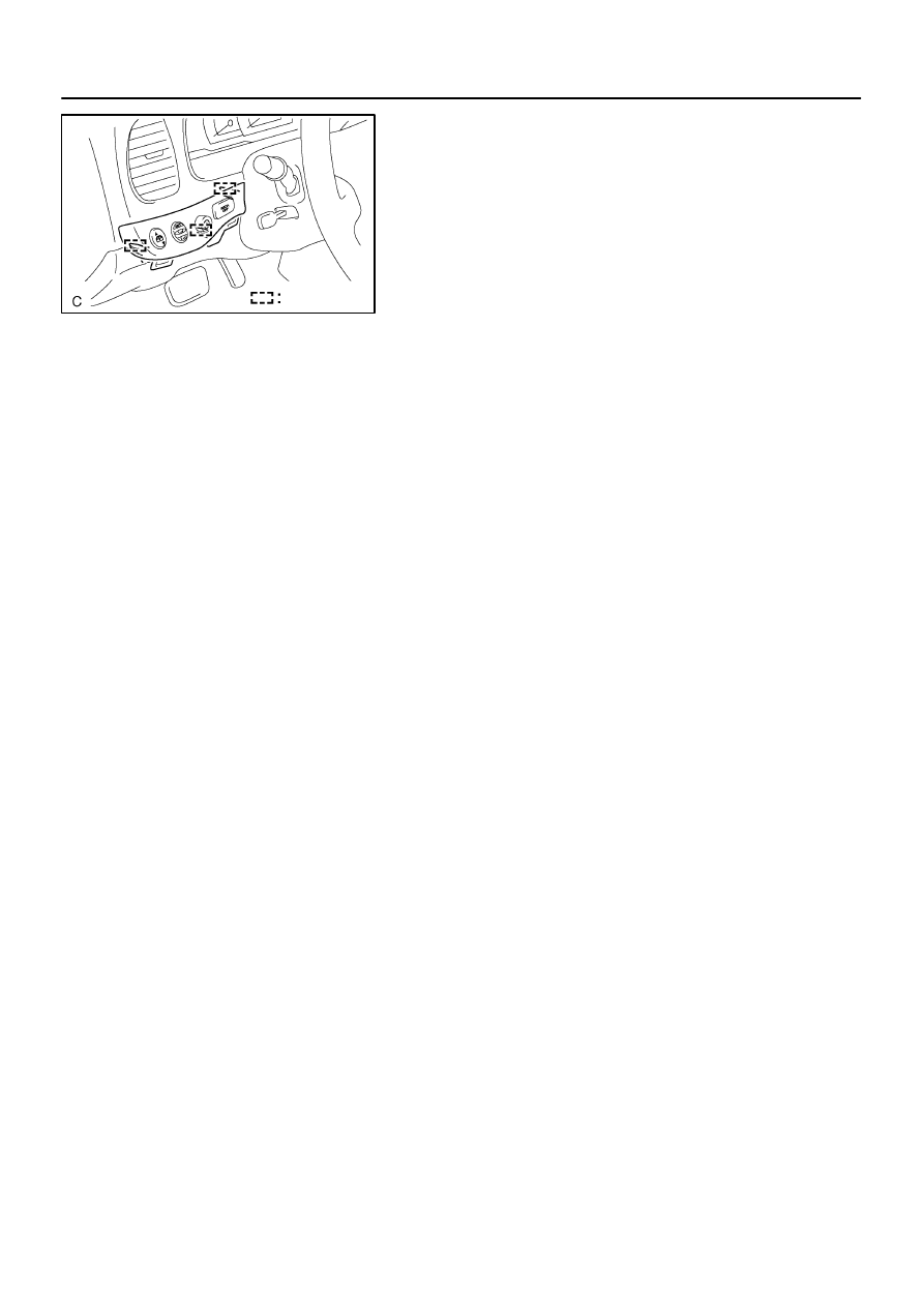
Claw
RS–118
–
SUPPLEMENTAL RESTRAINT SYSTEM
RSCA OFF SWITCH
3401
INSTALLATION
1.
INSTALL SWITCH BASE
(a)
Connect the connectors.
(b)
Engage the 3 claws to install the switch base.
2.
INSTALL LOWER FINISH PANEL (SEE PAGE
3.
CONNECT CABLE TO NEGATIVE BATTERY TERMI-
NAL
4.
PERFORM INITIALIZATION (SEE PAGE
Some system need initialization when disconnecting the cable
from the negative battery terminal.
5.