содержание .. 685 686 687 688 ..
Toyota Sequoia (2005). Manual - part 687
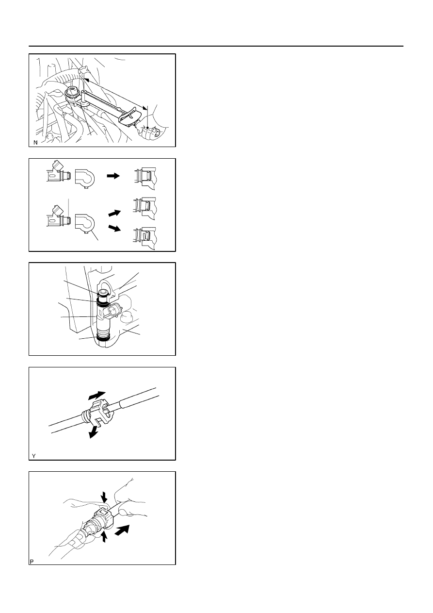
B16499
Fulcrum
Length
30 cm
SST
B02714
CORRECT
WRONG
Delivery Pipe
O–Ring
B04939
Delivery
Pipe
Intake
Manifold
O–Ring
Grommet
Injector
Insulator
B17532
Quick Type
Disconnect
B11684
Quick Type
Push
Pull
–
SFI
SFI SYSTEM
SF–3
2737
(3)
Using SST, tighten the union bolt to the specified
torque.
SST
09612–24014 (09617–24011)
Torque:
33 N·m (340 kgf·cm, 24 ft·lbf) for use with SST
39 N·m (400 kgf·cm, 29 ft·lbf)
HINT:
Use a torque wrench with a fulcrum length of 30 cm (11.81 in.).
(c)
Observe the following precautions when removing or
installing the injectors.
(1)
Never reuse the O–ring.
(2)
When placing a new O–ring on the injector, take
care not to damage it in any way.
(3)
Coat a new O–ring with spindle oil or gasoline be-
fore installing. Never use engine, gear or brake oil.
(d)
Install the injector to the delivery pipe and intake manifold
as shown in the illustration.
Before installing the injector, apply spindle oil or gasoline
on the place where the delivery pipe or the intake man-
ifold touches the O–ring of the injector.
(e)
Observe the following when disconnecting the fuel tube
connector (quick type):
(1)
Check if there is any dirt in the pipe and around the
connector before disconnecting the fuel tube con-
nector. If necessary, clean the dirt away.
(2)
Disconnect the fuel pipe clamp from the connector.
(3)
Be sure to disconnect them by hand.
(4)
When the connector and the pipe are stuck, push
and pull the connector. Then disconnect and pull it
out. Do not use any tools at this time.
(5)
Check if there is any dirt or other foreign matter on
the seal surface of the disconnected pipe. If neces-
sary, clean the dirt away.
(6)
Do not damage the disconnected pipe and connec-
tor and prevent intrusion of foreign objects by cover-
ing them with a plastic bag.