содержание .. 615 616 617 618 ..
Toyota Sequoia (2005). Manual - part 617
I28747
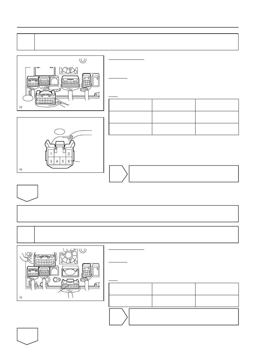
Radio and Navigation Assy
Wire Harness View:
R30
ILL–
I28577
R6
Light Control Rheostat
Wire Harness View:
ILL–
I28750
R27
SWG
Wire Harness View:
–
DIAGNOSTICS
NAVIGATION SYSTEM
DI–2263
2457
3
Check harness and connector (Radio and navigation assy – light control rheo-
stat).
PREPARATION:
Disconnect the radio and navigation assy and light control rheo-
stat connectors.
CHECK:
Measure the resistance according to the value(s) in the table
below.
OK:
Symbol
(Tester connection)
Condition
Specified condition
ILL– (R30–12) –
ILL– (R6–6)
Always
Below 1
Ω
ILL– (R30–12) –
Body ground
Always
10 k
Ω
or higher
NG
Repair or replace wire harness or connector.
OK
Replace radio and navigation assy.
4
Check radio and navigation assy.
PREPARATION:
Disconnect the radio and navigation assy connector.
CHECK:
Measure the voltage according to the value(s) in the table be-
low.
OK:
Symptom
(Tester connection)
Condition
Specified condition
SWG (R27–6) –
Body ground
Light control switch TAIL
10 to 14 V
OK
Replace radio and navigation assy.
NG