Toyota Sequoia (2005). Manual - part 592


  Главная      Automobile - Toyota     Toyota Sequoia - Repair manual 2005 year


поиск по сайту           правообладателям


содержание   ..  590  591  592  593   ..


Toyota Sequoia (2005). Manual - part 592


I28198

I28199

I28200

I28201

I28202

DIAGNOSTICS

NAVIGATION SYSTEM

DI–2163

2357

(4)

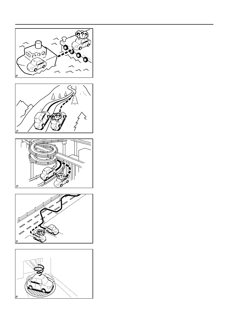
When the vehicle is carried, such as on a ferry, and
the vehicle itself is not running, the current vehicle
position mark may be displayed in the position
where the vehicle was until a measurement can be
performed by GPS.

(5)

When the vehicle runs on a steep hill, the current ve-
hicle position mark may deviate from the correct
position.

(6)

When the vehicle makes a continuous turn of 360,
720, 1,080, etc. degrees, the current vehicle posi-
tion mark may deviate from the correct position.

(7)

When the vehicle moves erratically, such as
constant lane changes, the current vehicle position
mark may deviate from the correct position.

(8)

When the ignition switch is turned to the ACC or ON
position on a turntable before parking, the current
vehicle position mark may not point in the correct
direction. The same will occur when the vehicle
comes out of parking.

I28203

I28204

I28187

Radio and Display Assy

Navigation ECU

Radio and Navigation Assy

DI–2164

DIAGNOSTICS

NAVIGATION SYSTEM

2358

(9)

When the vehicle runs on the snowy road or a
mountain path with the chains installed or using a
spare tire, the current vehicle position mark may
deviate from the correct position.

(10) When a tire is changed, the current vehicle position

mark may deviate from the correct position.

HINT:


Diameter of the tire may change, causing a speed sensor
error.


Performing the ”tire change” in calibration mode will allow
the system to correct the current vehicle position faster.

2.

Radio and navigation assy outline

Conventionally, 2 separate devices, a ”radio and display assy” and a ”navigation ECU” are used. This model
has adopted a new type, combining these devices into a single unit.

I28188

GPS satellite

Navigation

Gyro Sensor

ECU

GPS Antenna

Receive satellite
radio wave

GPS correction

Create the current
vehicle position
tracking data

Navigation screen

Map disc

Map matching
correction

Detect direction
change

Detect vehicle
running distance

Radio and Navigation Assy

Detect the
measurement position

Map scrolling
Map scale switching

Map and current vehicle 

position data processing

Vehicle Speed Sensor

GPS Antenna

Vehicle Speed Sensor

Location by
GPS navigation

Gyro Sensor

Location by
autonomous navigation

DIAGNOSTICS

NAVIGATION SYSTEM

DI–2165

2359

3.

Navigation system outline

(a)

Vehicle position tracking methods
It is essential that the navigation system correctly tracks the current vehicle position and displays it on
the map. There are 2 methods to track the current vehicle position: autonomous (dead reckoning) and
GPS* (satellite) navigation. Both navigation methods are used in conjunction with each other.
*GPS (Global Positioning System)

I28189

Navigation performed even where the
GPS radio wave does not reach.


 In a tunnel


 In an indoor parking lot


 Between tall buildings


 Under an overpass


 On a forest or tree–lined path

Autonomous navigation

Autonomous navigation and
GPS navigation

GPS satellite

DI–2166

DIAGNOSTICS

NAVIGATION SYSTEM

2360

Operation

Description

Vehicle Position Calculation

The navigation ECU calculates the current vehicle position (direction and current
position) using the direction deviation signal from the gyro sensor and the running
distance signal from the vehicle speed sensor and creates the driving route.

Map Display processing

The navigation ECU displays the vehicle track on the map by processing the ve-
hicle position data, vehicle running track, and map data from the map disc.

Map Matching

The map data from the map disc is compared to the vehicle position and running
track data. Then, the vehicle position is matched with the nearest road.

GPS Correction

The vehicle position is matched to the position measured by GPS. Then, the mea-
surement position data from the GPS unit is compared with the vehicle position and
running track data. If the position is widely different, the GPS measurement position
is used.

Distance Correction

The running distance signal from the vehicle speed sensor includes the error
caused by tire wear and slippage between the tires and road surface. Distance
correction is performed to account for this. The navigation ECU automatically off-
sets the running distance signal to make up for the difference between it and the
distance data of the map. The offset is automatically updated.

HINT:
The combination of autonomous and GPS navigation makes it possible to display the vehicle position even
when the vehicle is in places where the GPS radio wave cannot receive a signal. When only autonomous
navigation is used, however, the mapping accuracy may slightly decline.


содержание   ..  590  591  592  593   ..