содержание .. 577 578 579 580 ..
Toyota Sequoia (2005). Manual - part 579
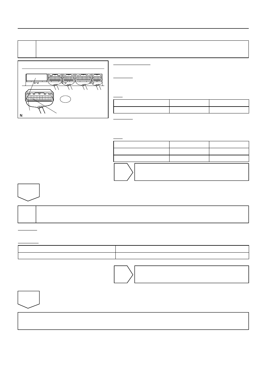
I28614
+B1
ACC
GND
R23
Multi–display Controller Sub–assy:
–
DIAGNOSTICS
REAR SEAT ENTERTAINMANT SYSTEM
DI–2111
2305
INSPECTION PROCEDURE
1
Inspect multi–display controller sub–assy (+B1, ACC, GND).
PREPARATION:
Disconnect the R23 connector.
CHECK:
Measure the resistance according to the value(s) in the table
below.
OK:
Symbol (Tester connection)
Condition
Specified condition
GND (R23–29) – Body ground
Always
Below 1
Ω
CHECK:
Measure the voltage according to the value(s) in the table be-
low.
OK:
Symbol (Tester connection)
Condition
Specified condition
+B1 (R23–16) – GND (R23–29)
Always
10 to 14 V
ACC (R23–32) – GND (R23–29)
Ignition SW ACC
10 to 14 V
NG
Repair or replace harness or connector.
OK
2
Check problem symptoms table.
CHECK:
Check the problem symptoms table.
RESULT:
All possible suspected areas have been inspected
Go to step A
Possible suspected areas still exist
Go to step B
B
Proceed to next circuit inspection shown in
problem symptoms table or diagnostic trouble
code chart (See page
A
Replace multi–display controller sub–assy.