содержание .. 574 575 576 577 ..
Toyota Sequoia (2005). Manual - part 576
DIDB2–01
I28276
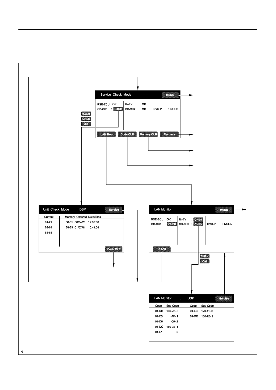
”Diagnosis MENU”
to section
Recheck
History clearance
DTC memory clearance
DTC clear
–
DIAGNOSTICS
REAR SEAT ENTERTAINMANT SYSTEM
DI–2099
2293
CHECK MODE PROCEDURE
SERVICE CHECK MODE
HINT:
Service Check Mode is operated as follows.