содержание .. 504 505 506 507 ..
Toyota Sequoia (2005). Manual - part 506
DIDET–01
I18630
F18
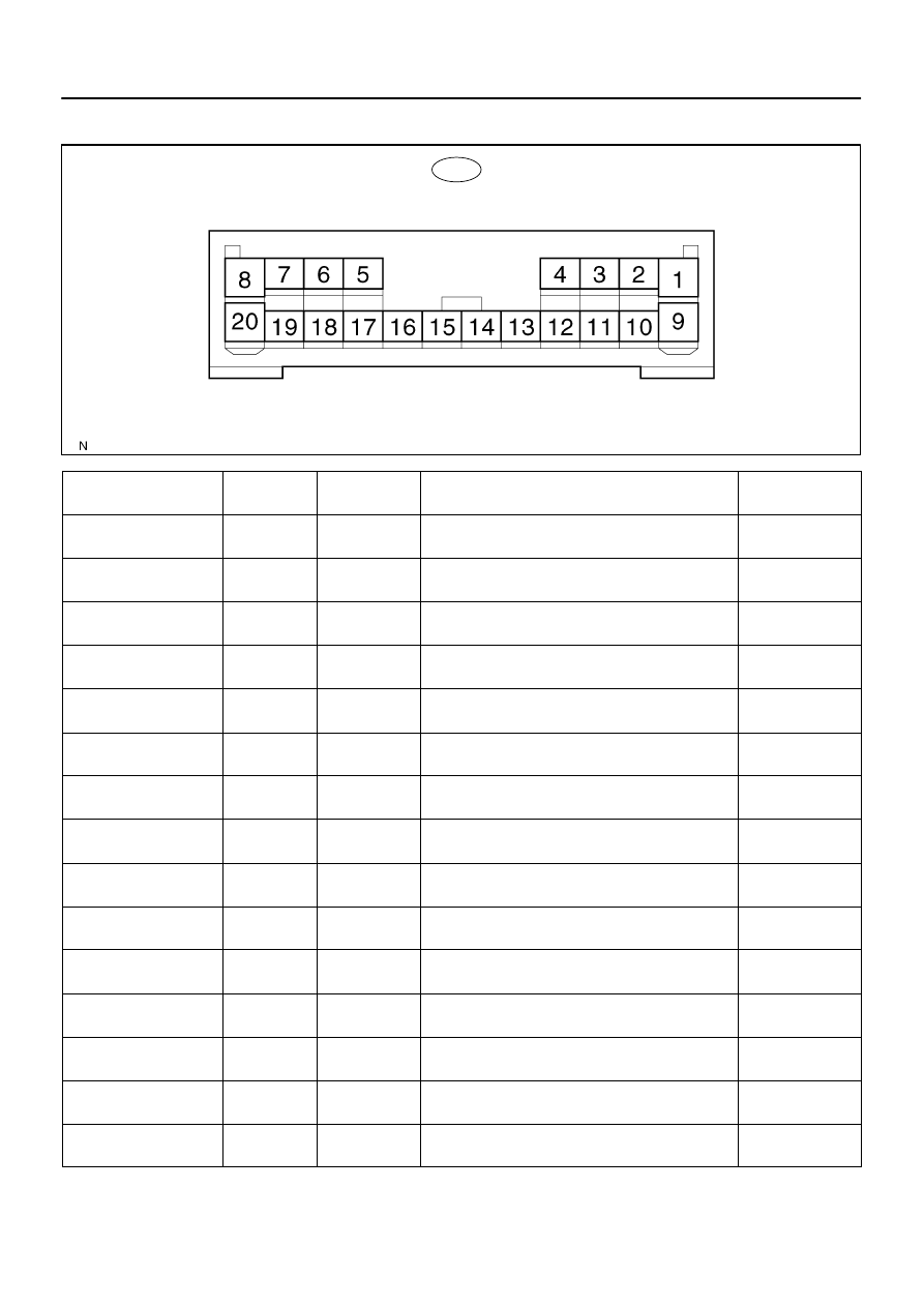
PASSENGER DOOR ECU
(w/o Driving Position Memory):
–
DIAGNOSTICS
PASSENGER DOOR CONTROL SYSTEM
DI–1819
2013
TERMINALS OF ECU
Symbols (Terminal No.)
Wiring Color
Terminal De-
scription
Condition
Specified Condition
BDR
↔
GND
(20
↔
8)
L–Y
↔
W–B
Battery
Always
10 to 14 V
CPUB
↔
GND
(12
↔
8)
W–R
↔
W–B
Battery
Always
10 to 14 V
SIG
↔
GND
(19
↔
8)
B–R
↔
W–B
Ignition switch
Ignition switch ON
10 to 14 V
GND
↔
Body Ground
(8
↔
Body ground)
W–B
↔
Body
Ground
Ground
Always
Below 1 V
PLS
↔
SGND
(17
↔
18)
L–R
↔
W–B
Power window
pulse sensor
Power window is operated
Pulse generation
PLS
↔
SGND
(17
↔
18)
L–R
↔
W–B
Power window
pulse sensor
Power window is not operated (Switch ON)
Below 1 V
PLS
↔
SGND
(17
↔
18)
L–R
↔
W–B
Power window
pulse sensor
Power window is not operated (Switch OFF)
10 to 14 V
LMT
↔
SGND
(16
↔
18)
L–W
↔
W–B
Power window
limit switch
Front passenger’s door window not fully closed position
Below 1 V
LMT
↔
SGND
(16
↔
18)
L–W
↔
W–B
Power window
limit switch
Front passenger’s door window fully closed position
10 to 14 V
PU
↔
PDN
(1
↔
9)
R
↔
G
Power window
motor (UP)
Ignition switch ON and front passenger’s window switch
OFF
Below 1 V
PU
↔
PDN
(1
↔
9)
R
↔
G
Power window
motor (UP)
Ignition switch ON and front passenger’s window switch
UP
10 to 14 V
PDN
↔
PU
(9
↔
1)
G
↔
R
Power window
motor (DOWN)
Ignition switch ON and front passenger’s window switch
OFF
Below 1 V
PDN
↔
PU
(9
↔
1)
G
↔
R
Power window
motor (DOWN)
Ignition switch ON and front passenger’s window switch
DOWN
10 to 14 V
MPX1
↔
–
(10
↔
–)
B
↔
–
Multiplex com-
munication line
Multiplex communication circuit
–
MPX2
↔
–
(11
↔
–)
G–B
↔
–
Multiplex com-
munication line
Multiplex communication circuit
–