содержание .. 476 477 478 479 ..
Toyota Sequoia (2005). Manual - part 478
–
DIAGNOSTICS
BODY CONTROL SYSTEM
DI–1707
1901
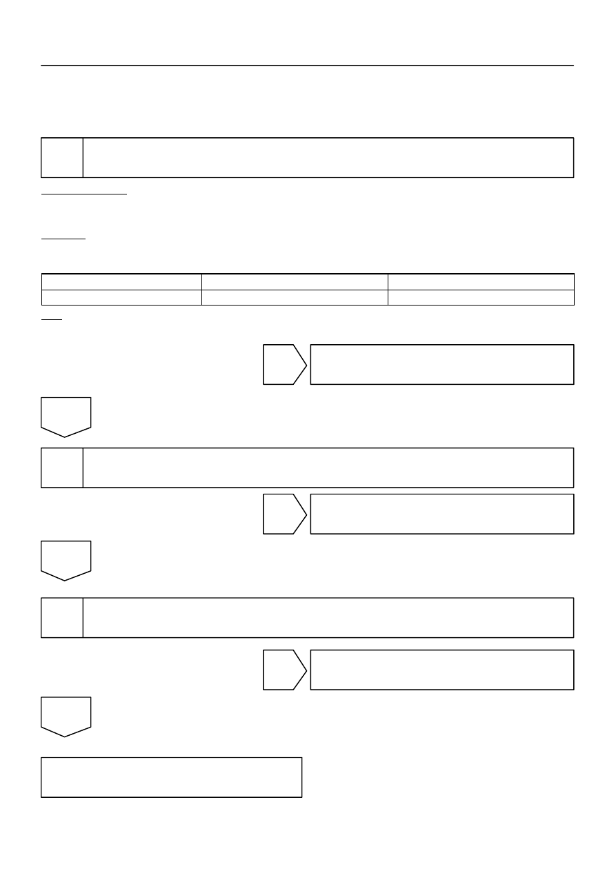
INSPECTION PROCEDURE
HINT:
When using the hand–held tester, start the inspection from step 1 and when not using the hand–held tester,
start from step 2.
1
Check TAILLIGHT relay using hand–held tester.
PREPARATION:
(a)
Connect the hand–held tester to the DLC3.
(b)
Turn the ignition switch ON.
CHECK:
According to the display on the tester, perform the ”ACTIVE TEST”.
BODY ECU:
Item
Test Details
Diagnostic Note
TAIL LIGHT
Taillight ON/OFF
–
OK:
The taillights turn on or off correctly when operating them through the hand–held tester.
OK
Proceed to next circuit inspection shown in
problem symptoms table (See page
NG
2
Check TAILLIGHT relay (See page
).
NG
Replace TAILLIGHT relay.
OK
3
Check wire harness and connector between TAILLIGHT relay and body ECU, bat-
tery and TAILLIGHT relay (See page
NG
Repair or replace wire harness or connector.
OK
Proceed to next circuit inspection shown in
problem symptoms table
(See page