содержание .. 468 469 470 471 ..
Toyota Sequoia (2005). Manual - part 470
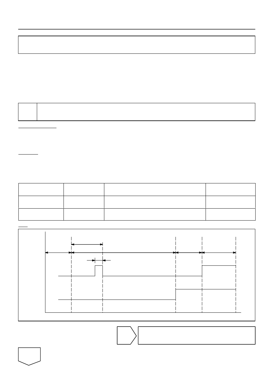
Limit
Switch
No. 1
Sliding
Roof
Status
Fully
Opened
Sliding
Fully
Closed
Tilting
Limit
Switch
No. 2
250 mm point from fully
opened position
About 10 mm
–
DIAGNOSTICS
SLIDING ROOF SYSTEM
DI–1675
1869
Sliding Roof Pulse Plate Circuit
WIRING DIAGRAM
See page
INSPECTION PROCEDURE
HINT:
If not using the hand–held tester, start from STEP 3.
1
Check sliding roof pulse plate operation.
PREPARATION:
(a)
Connect the hand–held tester to the DLC3.
(b)
Turn ignition switch ON and hand–held tester main switch ON.
(c)
Select the DATA LIST mode on the hand–held tester.
CHECK:
(a)
Operate the sliding roof.
(b)
At this time, check that status (ON/OFF) of limit switch 1 and limit switch 2 changes on the hand–held
tester screen as shown in the chart below.
SLIDE ROOF:
Item
Measurement Item/
Display (Range)
Normal condition
Diagnostic Note
LIMIT SW 1
Position SW NO.1/
ON or OFF
ON: 250 mm point from fully opened position
OFF: Sliding roof fully closed position
–
LIMIT SW 2
Position SW NO.2/
ON or OFF
ON: Sliding roof fully closed position
OFF: Sliding roof except fully closed position
–
OK:
NG
Replace sliding roof gear assembly.
OK
DI279–11