содержание .. 459 460 461 462 ..
Toyota Sequoia (2005). Manual - part 461
I28461
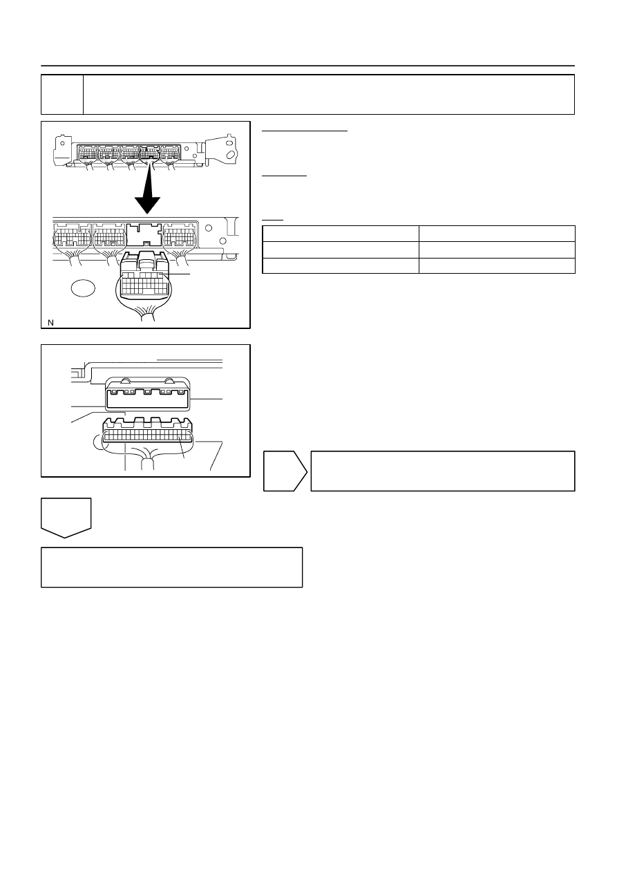
ECM:
E5
TACH
I28569
C5–23
Combination Meter:
–
DIAGNOSTICS
COMBINATION METER SYSTEM
DI–1639
1833
4
Check harness and connector (ECM – combination meter).
PREPARATION:
(a)
Disconnect the C5 connector of the combination meter.
(b)
Disconnect the E5 connector of the ECM.
CHECK:
Measure the resistance according to the value(s) in the table
below.
OK:
Tester Connection (Symbol)
Specified Condition
C5–23 – E5–1 (TACH)
Below 1
Ω
C5–23 – Body ground
10 k
Ω
or higher
NG
Repair or replace harness or connector.
OK
Replace ECM (See page