содержание .. 391 392 393 394 ..
Toyota Sequoia (2005). Manual - part 393
H41440
H23351
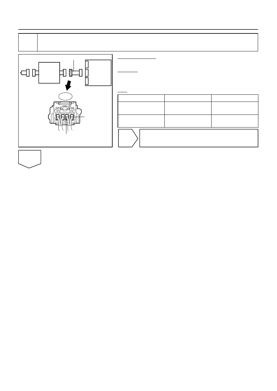
D Squib
Spiral
Cable
Airbag
Sensor
Assembly
D+
D–
C
D
E
F
A
B
Cowl Wire
A23
–
DIAGNOSTICS
SUPPLEMENTAL RESTRAINT SYSTEM
DI–1367
1561
17
Check cowl wire (short to ground).
PREPARATION:
Disconnect the cowl wire connector from the spiral cable.
CHECK:
Measure the resistance according to the value(s) in the table
below.
OK:
Tester Connection
Condition
Specified Condition
A23–1 (D+) –
Body ground
Always
1 M
Ω
or higher
A23–2 (D–) –
Body ground
Always
1 M
Ω
or higher
NG
Repair or replace cowl wire.
OK