Toyota Sequoia (2005). Manual - part 354


  Главная      Automobile - Toyota     Toyota Sequoia - Repair manual 2005 year


поиск по сайту           правообладателям


содержание   ..  352  353  354  355   ..


Toyota Sequoia (2005). Manual - part 354


C84211

H24024

H24005

Occupant
Classification
ECU

Airbag
Sensor
Assembly

A

FSR+

FSR–

B

C

D

E

F

BL1

Seat Wire No. 1

Floor Wire

DIAGNOSTICS

SUPPLEMENTAL RESTRAINT SYSTEM

DI–1211

1405

11

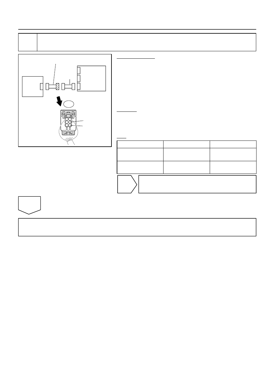
Check seat wire No. 1 (short to B+).

PREPARATION:
(a)

Turn the ignition switch to the LOCK position.

(b)

Disconnect the negative (–) terminal cable from the bat-
tery, and wait for at least for 90 seconds.

(c)

Disconnect the seat wire No. 1 connector from the floor
wire.

(d)

Connect the negative (–) terminal cable to the battery,
and wait for at least 2 seconds.

CHECK:
(a)

Turn the ignition switch to the ON position.

(b)

Measure the voltage according to the value(s) in the table
below.

OK:

Tester Connection

Condition

Specified Condition

BL1–3 (FSR+) – 

Body ground

Ignition switch ON

Below 1 V

BL1–5 (FSR–) – 

Body ground

Ignition switch ON

Below 1 V

NG

Repair or replace seat wire No. 1.

OK

Repair or replace floor wire.

C84211

H24024

H24005

Occupant
Classification
ECU

Airbag
Sensor
Assembly

A

FSR+

FSR–

B

C

D

E

F

BL1

Seat Wire No. 1

Floor Wire

DI–1212

DIAGNOSTICS

SUPPLEMENTAL RESTRAINT SYSTEM

1406

12

Check seat wire No. 1 (short to ground).

PREPARATION:
Disconnect the seat wire No. 1 connector from the floor wire.
CHECK:
Measure the resistance according to the value(s) in the table
below.
OK:

Tester Connection

Condition

Specified Condition

BL1–3 (FSR+) – 

Body ground

Always

1 M

 or higher

BL1–5 (FSR–) – 

Body ground

Always

1 M

 or higher

NG

Repair or replace seat wire No. 1.

OK

Repair or replace floor wire.

H23993

Airbag Sensor Assembly

A19

9

LSP+

W

VS

GND

Seat
Position
Airbag
Sensor
Assembly

B18 (*1)
Buckle SW LH
Seat Position Airbag Sensor Assembly

A19

17

LSP–

B

3

5

*1: The connectors of the seat position airbag sensor assembly and the
front seat inner belt LH (buckle switch LH) are in common use.

DIAGNOSTICS

SUPPLEMENTAL RESTRAINT SYSTEM

DI–1213

1407

DTC

B1653/35 Seat Position Sensor Assembly 

Malfunction

CIRCUIT DESCRIPTION

The seat position airbag sensor assembly circuit consists of the airbag sensor assembly and the seat posi-
tion airbag sensor assembly.
DTC B1653/35 is recorded when a malfunction is detected in the seat position sensor assembly circuit.

DTC No.

DTC Detection Condition

Trouble Area

B1653/35


The airbag sensor assembly receives a line short circuit

signal, an open circuit signal, a short circuit to ground sig-

nal or a short circuit to B+ signal in the seat position sen-

sor assembly circuit for 2 seconds.


Seat position airbag sensor assembly malfunction


Airbag sensor assembly malfunction


Seat position airbag sensor assembly


Airbag sensor assembly


Floor wire No. 2

WIRING DIAGRAM

DIDGZ–01

H10600

H01007

H43920

H23364

DLC3

CG

TC

DTC B1653/35

Seat
Position
Airbag
Sensor
Assembly

Airbag 
Sensor 
Assembly

DI–1214

DIAGNOSTICS

SUPPLEMENTAL RESTRAINT SYSTEM

1408

INSPECTION PROCEDURE

CAUTION:
Be sure to perform the following procedures before troubleshooting to avoid unexpected airbag de-
ployment.
(a)

Turn the ignition switch to the LOCK position.

(b)

Disconnect the negative (–) terminal cable from the battery, and wait for at least 90 seconds.

(c)

Disconnect the connectors from the airbag sensor assembly.

(d)

Disconnect the connectors from the steering wheel pad.

(e)

Disconnect the connectors from the front passenger airbag assembly.

(f)

w/ Side and curtain shield airbag:
Disconnect the connectors from the side airbag assembly LH and RH.

(g)

w/ Side and curtain shield airbag:
Disconnect the connectors from the curtain shield airbag assembly LH and RH.

(h)

Disconnect the connectors from the front seat outer belt LH and RH.

1

Check DTC.

PREPARATION:
(a)

Connect the connectors to the airbag sensor assembly.

(b)

Connect the negative (–) terminal cable to the battery,
and wait for at least 2 seconds.

CHECK:
(a)

Turn the ignition switch to the ON position, and wait for at
least 60 seconds.

(b)

Clear the DTCs stored in memory (see page 

DI–1147

).

(c)

Turn the ignition switch to the LOCK position.

(d)

Turn the ignition switch to the ON position, and wait for at
least 60 seconds.

(e)

Check the DTCs (see page 

DI–1147

).

OK:

DTC B1653/35 is not output.

HINT:
Codes other than DTC B1653/35 may be output at this time, but
they are not related to this check.

NG

Go to step 2.

OK

From the results of the above inspection, the malfunctioning part can now be considered normal.
To make sure of this, use the simulation method to check (see page 

DI–1137

).


содержание   ..  352  353  354  355   ..