содержание .. 340 341 342 343 ..
Toyota Sequoia (2005). Manual - part 342
H02757
H10600 H40103
H23566
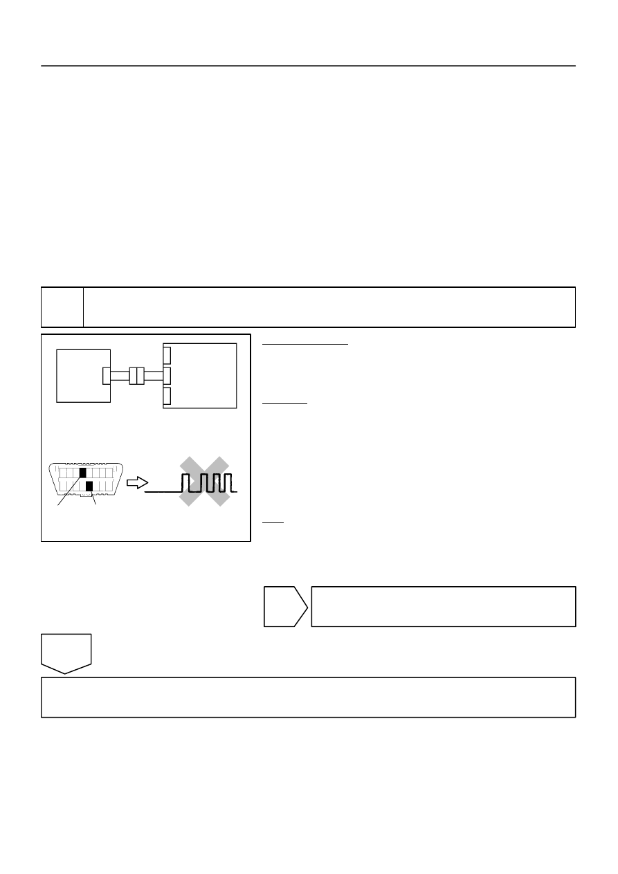
CG
TC
DTC B1610/13
DLC3
Front Airbag
Sensor RH
Airbag
Sensor
Assembly
–
DIAGNOSTICS
SUPPLEMENTAL RESTRAINT SYSTEM
DI–1163
1357
INSPECTION PROCEDURE
CAUTION:
Be sure to perform the following procedures before troubleshooting to avoid unexpected airbag de-
ployment.
(a)
Turn the ignition switch to the LOCK position.
(b)
Disconnect the negative (–) terminal cable from the battery, and wait for at least 90 seconds.
(c)
Disconnect the connectors from the airbag sensor assembly.
(d)
Disconnect the connectors from the steering wheel pad.
(e)
Disconnect the connectors from the front passenger airbag assembly.
(f)
w/ Side and curtain shield airbag:
Disconnect the connectors from the side airbag assembly LH and RH.
(g)
w/ Side and curtain shield airbag:
Disconnect the connectors from the curtain shield airbag assembly LH and RH.
(h)
Disconnect the connectors from the front seat outer belt LH and RH.
1
Check DTC.
PREPARATION:
(a)
Connect the connectors to the airbag sensor assembly.
(b)
Connect the negative (–) terminal cable to the battery,
and wait for at least 2 seconds.
CHECK:
(a)
Turn the ignition switch to the ON position, and wait for at
least 60 seconds.
(b)
Clear the DTCs stored in memory (see page
(c)
Turn the ignition switch to the LOCK position.
(d)
Turn the ignition switch to the ON position, and wait for at
least 60 seconds.
(e)
OK:
DTC B1610/13 is not output.
HINT:
Codes other than DTC B1610/13 may be output at this time, but
they are not related to this check.
NG
Go to step 2.
OK
From the results of the above inspection, the malfunctioning part can now be considered normal.
To make sure of this, use the simulation method to check (see page