Toyota Sequoia (2005). Manual - part 261


  Главная      Automobile - Toyota     Toyota Sequoia - Repair manual 2005 year


поиск по сайту           правообладателям


содержание   ..  259  260  261  262   ..


Toyota Sequoia (2005). Manual - part 261


DIAGNOSTICS

TIRE PRESSURE WARNING SYSTEM

DI–839

1033

9

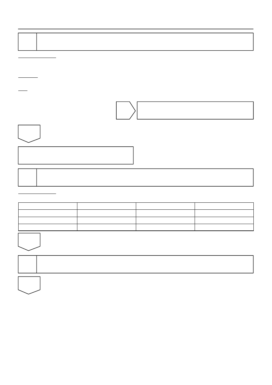
Replace tire pressure monitor ECU and check DTC.

PREPARATION:
(a)

Replace the tire pressure monitor ECU (see page 

SA–20

).

(b)

Clear the DTCs.

CHECK:
Check for a DTC.
OK:

DTC is not output.

NG

Replace tire pressure monitor valve sub–assy
(See page 

SA–16

).

OK

End

10

Set tire pressure to normal value.

PREPARATION:
Set the tire pressure of all wheels to the specified value.

Tire size

Front

Rear

Spare

P245 / 70 R 16

220 kPa (2.2 kgf/cm

2

, 32 psi)

240 kPa (2.4 kgf/cm

2

, 35 psi)

240 kPa (2.4 kgf/cm

2

, 35 psi)

P265 / 70 R 16

220 kPa (2.2 kgf/cm

2

, 32 psi)

220 kPa (2.2 kgf/cm

2

, 32 psi)

220 kPa (2.2 kgf/cm

2

, 32 psi)

P265 / 65 R 17

220 kPa (2.2 kgf/cm

2

, 32 psi)

220 kPa (2.2 kgf/cm

2

, 32 psi)

220 kPa (2.2 kgf/cm

2

, 32 psi)

NEXT

11

Identify transmitter corresponding to DTC (See page 

DI–881

).

NEXT

F19140

Example:

A

B

Front

F19139

Example:

Front

A

DI–840

DIAGNOSTICS

TIRE PRESSURE WARNING SYSTEM

1034

12

Interchange tires.

PREPARATION:
Interchange tire ”A” with a defective tire pressure monitor valve
sub–assy with tire ”B” with a normal one.
HINT:
If tire ”A” (left front ) is identified in step 11.

NEXT

13

Set tire pressure to normal value.

PREPARATION:
Set the tire pressure of all wheels to the specified value.

Tire size

Front

Rear

Spare

P245 / 70 R 16

220 kPa (2.2 kgf/cm

2

, 32 psi)

240 kPa (2.4 kgf/cm

2

, 35 psi)

240 kPa (2.4 kgf/cm

2

, 35 psi)

P265 / 70 R 16

220 kPa (2.2 kgf/cm

2

, 32 psi)

220 kPa (2.2 kgf/cm

2

, 32 psi)

220 kPa (2.2 kgf/cm

2

, 32 psi)

P265 / 65 R 17

220 kPa (2.2 kgf/cm

2

, 32 psi)

220 kPa (2.2 kgf/cm

2

, 32 psi)

220 kPa (2.2 kgf/cm

2

, 32 psi)

NEXT

14

Forcibly transmit transmitter ID.

PREPARATION:
Remove the valve core of tire ”A”, rapidly reduce the tire pres-
sure and forcibly transmit the transmitter ID of the tire pressure
monitor valve sub–assy.

NEXT

DIAGNOSTICS

TIRE PRESSURE WARNING SYSTEM

DI–841

1035

15

Check DTC again (See page 

DI–820

).

CHECK:
Check for a DTC.
OK:

DTC is not output.

HINT:


If a DTC is output, replace the identified tire pressure monitor valve sub–assy.


Before installing a new tire pressure monitor valve sub–assy, read and write down its transmitter ID.


Register the transmitter ID after replacement and then set the tire pressure to the specified value (see
page 

DI–805

).

NG

Replace tire pressure monitor valve sub–assy
(See page 

SA–16

).

OK

Replace tire pressure monitor receiver assy
(See page 

SA–13

).

DI–842

DIAGNOSTICS

TIRE PRESSURE WARNING SYSTEM

1036

DTC

C2141/41 Transmitter ID1 Error

DTC

C2142/42 Transmitter ID2 Error

DTC

C2143/43 Transmitter ID3 Error

DTC

C2144/44 Transmitter ID4 Error

DTC

C2145/45 Transmitter ID5 Error

CIRCUIT DESCRIPTION

DTC No.

DTC Detecting Condition

Trouble Area

C2141/41
C2142/42
C2143/43
C2144/44
C2145/45

If an ”ERROR” signal is received 3 times consecutively, the
tire pressure monitor valve sub–assy will be judged as de-
fective and these DTCs will be output.
This will happen under the situations where the inflation
pressure is out of the specified range 0 to 637.5 kPa (0 to
6.48 kgf/cm

2

, 0 psi to 92.2 psi), the temperature inside the

tire is out of the specified range –40 to 215


C (–40 to 419


F), or an error occurs in the tire pressure monitor valve

sub–assy, etc.


Tire pressure monitor valve sub–assy


Tire pressure monitor ECU


Tire pressure monitor receiver assy

HINT:
It is necessary to perform the procedure to identify the tire pressure monitor valve sub–assy that is malfunc-
tioning because it cannot be identified by the output DTC.

DIDK9–01


содержание   ..  259  260  261  262   ..