Toyota Sequoia (2005). Manual - part 248


  Главная      Automobile - Toyota     Toyota Sequoia - Repair manual 2005 year


поиск по сайту           правообладателям


содержание   ..  246  247  248  249   ..


Toyota Sequoia (2005). Manual - part 248


I27705

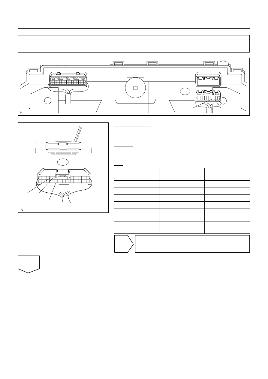
Combination Meter Wire Harness View:

C6

C6–16

C6–15

C6–14

F16805

Suspension Control ECU
Wire Harness View:

S25

NR

HI

LO

DIAGNOSTICS

AIR SUSPENSION SYSTEM

DI–787

981

2

Check harness and connector (Suspension control ECU – Combination meter
assy).

PREPARATION:
Disconnect the suspension control ECU connector and the
combination meter connector.
CHECK:
Measure the resistance according to the value(s) in the table
below.
OK:

Tester connection

(Symbol)

Condition

Specified condition

S25–8 (HI) – C6–16

Always

Below 1 

S25–9 (NR) – C6–15

Always

Below 1 

S25–26 (LO) – C6–14

Always

Below 1 

S25–8 (HI) – Body ground

Always

10 k

 or higher

S25–9 (NR) – 

Body ground

Always

10 k

 or higher

S25–26 (LO) –

Body ground

Always

10 k

 or higher

NG

Repair or replace harness or connector.

OK

F16805

Suspension Control ECU
Wire Harness View:

S25

NR

HI

LO

DI–788

DIAGNOSTICS

AIR SUSPENSION SYSTEM

982

3

Check combination meter.

PREPARATION:
Reconnect the combination meter connector.
CHECK:
Measure the voltage according to the value(s) in the table be-
low.
OK:

Tester connection

(Symbol)

Condition

Specified condition

S25–8 (HI) – Body ground

Ignition switch ON

10 to 14 V

S25–9 (NR) – 

Body ground

Ignition switch ON

10 to 14 V

S25–26 (LO) – 

Body ground

Ignition switch ON

10 to 14 V

NG

Replace combination meter.

OK

Replace suspension control ECU
(See page 

IN–35

).

F19451

C6
Combination
Meter

Suspension Control
ECU

I18
Ignition SW

Engine Room J/B

Instrument Panel J/B

B–O

W–R

11

7

1H

1J

IGN1

1C

1C

3

2

B–R

MAN.

24

13

LG

11

S25 VN

5

IG2

AM2

6

W–R

B

Battery

1

2D

AM2

2C

1

B

5

4

F10
FL Block

DIAGNOSTICS

AIR SUSPENSION SYSTEM

DI–789

983

Height Control Manual Indicator Lamp Circuit

CIRCUIT DESCRIPTION

When manual mode is selected by pressing the height control mode select switch, the manual indicator lamp
comes on. (For the wiring diagram of the height control mode select switch circuit, see page 

DI–778

.) If the

suspension control ECU detects a problem, the height control manual indicator lamp blinks while suspend-
ing the height control function. At the same time, the suspension control ECU records a DTC in the memory.

Connect terminals TC and CG of the DLC3 to make the height control manual indicator lamp blink and output
DTCs.

WIRING DIAGRAM

DIDEN–01

DI–790

DIAGNOSTICS

AIR SUSPENSION SYSTEM

984

INSPECTION PROCEDURE

1

Inspect height control manual indicator lamp.

PREPARATION:
Turn the ignition switch to the ON position.
CHECK:
Check that the height control manual indicator lamp comes on.
OK:

Height control manual indicator lamp comes on, and then goes off after 2 seconds.

NG

Go to combination meter
(See page 

DI–1610

).

OK


содержание   ..  246  247  248  249   ..