содержание .. 237 238 239 240 ..
Toyota Sequoia (2005). Manual - part 239
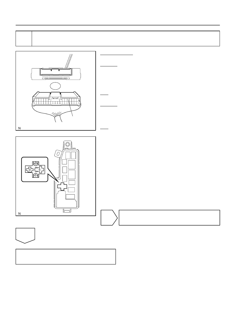
F16805
S25
Suspension Control ECU
Wire Harness View:
RC
F19460
Engine Room R/B No. 2:
AIR SUS
Relay Terminal
–
DIAGNOSTICS
AIR SUSPENSION SYSTEM
DI–751
945
3
Check harness and connector (Engine room R/B – Suspension control ECU,
Body ground).
PREPARATION:
Disconnect the ECU connector.
CHECK:
Check for an open or short circuit in the harness and the con-
nector between the AIR SUS relay terminal 1 of the engine
room R/B and terminal S25–5 (RC) of the suspension control
ECU.
OK:
There is no open or short in the wire harness.
CHECK:
Check for an open circuit in the harness and the connector be-
tween the AIR SUS relay terminal 2 of the engine room R/B and
body ground.
OK:
There is no open in the wire harness.
NG
Repair or replace harness or connector.
OK
Replace suspension control ECU
(See page
).