Toyota Sequoia (2005). Manual - part 233


  Главная      Automobile - Toyota     Toyota Sequoia - Repair manual 2005 year


поиск по сайту           правообладателям


содержание   ..  231  232  233  234   ..


Toyota Sequoia (2005). Manual - part 233


DIDDE–01

DIAGNOSTICS

AIR SUSPENSION SYSTEM

DI–727

921

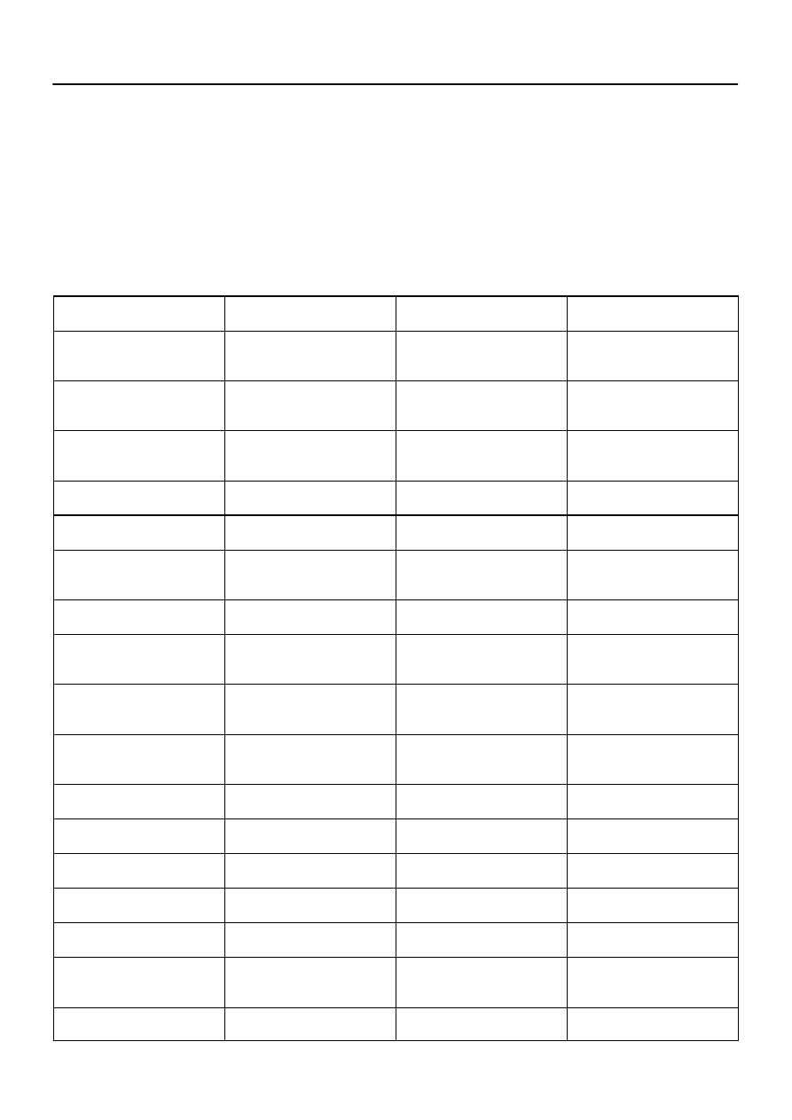
DATA LIST / ACTIVE TEST

1.

DATA LIST

HINT:
By accessing the DATA LIST displayed by the hand–held tester, you can read the value of the switches and
sensors and so on without removing any parts. Reading the DATA LIST is the first step of troubleshooting
and is one method to shorten labor time.
(a)

Connect the hand–held tester to the DLC3.

(b)

Turn the ignition switch to the ON position.

(c)

Following the display on the tester, read the DATA LIST.

AIR SUSPENSION:

Item

Measurement Item / Range (Dis-

play)

Normal Condition

Diagnostic Note

VEHICLE SPD

Vehicle speed reading / min.: 0

km/h (0 mph), max.: 255 km/h

(158 mph)

Actual vehicle speed

Speed indicated on the combina-

tion meter

FR WHEEL SPD

Wheel speed (Front right) reading /

min.: 0 km/h (0 mph), max.: 255

km/h (159 mph)

Actual vehicle speed

Speed indicated on the speedome-

ter

FL WHEEL SPD

Wheel speed (Front left) reading /

min.: 0 km/h (0 mph), max.: 255

km/h (159 mph)

Actual vehicle speed

Speed indicated on the speedome-

ter

IG VOLTAGE

ECU power supply voltage / min.:

0 V, max.: 25.5 V

Actual ECU power supply voltage:

10 to 14 V

POWER VOLTAGE

+B power source voltage / min.: 0

V, max.: 25.5 V

Actual battery power supply volt-

age: 10 to 14 V

STEERING ANG

Steering angle sensor reading /

min.: –49150.5 deg, max.: 49152

deg

Actual steering angle / 

Left turn: reading increases 

Right turn: reading increases

Zero point is set at the point when

battery is connected

ENGINE SPD

Crankshaft position sensor read-

ing / min.: 0 rpm, max.: 25,500 rpm

Actual engine speed

Speed indicated on the combina-

tion meter

HEIGHT SW DOWN

Height control switch (DOWN) /

ON or OFF

ON: Height control switch

”DOWN” button pressed

OFF: –

HEIGHT SW UP

Height control switch (UP) / ON or

OFF

ON: Height control switch ”UP”

button pressed

OFF: –

HEIGHT SW HOLD

Height control mode select switch

/ ON or OFF

ON: Height control mode select

switch pressed

OFF: –

STOP LIGHT SW

Stop light switch / ON or OFF

ON: Brake pedal depressed

OFF: Brake pedal released

DOOR SW

Door courtesy light switch / ON or

OFF

ON: Open each door

OFF: Close all doors

L4 SW

4LO switch / ON or OFF

ON: 2WD/4HI switch pressed

OFF: –

TS

TS terminal / ON or OFF

ON: During test mode

OFF: Normal mode

TC

TC terminal / ON or OFF

ON: DTC recorded

OFF: No DTC recorded

SOL SLRL

Height control valve solenoid (Lev-

elling solenoid valve) / ON or OFF

ON: Leveling solenoid operated

OFF: Leveling solenoid not oper-

ated

SOL SLRG

Height control valve solenoid

(Gate solenoid valve) / ON or OFF

ON: Gate solenoid operated

OFF: Gate solenoid not operated

DI–728

DIAGNOSTICS

AIR SUSPENSION SYSTEM

922

MAIN RELAY

MAIN relay / ON or OFF

ON: MAIN relay operated

OFF: MAIN relay not operated

MOTOR RELAY

AIR SUS relay / ON or OFF

ON: Compressor operated

OFF: Compressor not operated

RR HEIGHT

Right rear height control sensor

reading / min.: –3276.7 mm

(–129.004 in.), max.: 3276.8 mm

(129.008 in.)

Always: 0 mm (0 in.)

RL HEIGHT

Left rear height control sensor

reading / min.: –3276.7 mm

(–129.004 in.), max.: 3276.8 mm

(129.008 in.)

2WD:

Min.: –15 mm (–0.59 in.)

Max.: 40 mm (1.57 in.)

4WD:

Min.: –30 mm (–1.18 in.)

Max.: 40 mm (1.57 in.)

#CODES

Number of DTC recorded / min.: 0,

max.: 255

Min.: 0, Max.: XX

2.

ACTIVE TEST LIST

HINT:
Perform the ACTIVE TEST using the hand–held tester to operate the sensors, relays and solenoids without
removing any parts. Performing the ACTIVE TEST is the first step of troubleshooting and is one of the meth-
ods to shorten labor time. It is possible to display the DATA LIST during the ACTIVE TEST.
(a)

Connect the hand–held tester to the DLC3.

(b)

Turn the ignition switch to the ON position.

(c)

Following the display on the tester, perform the ACTIVE TEST.

AIR SUSPENSION:

Item

Vehicle Condition / Test Details

Diagnostic Note

RR HEIGHT

Turn height control switch / UP or DOWN

LEVEL SOL REAR

Turn leveling solenoid valve / ON or OFF

Operation sound of solenoid (clicking sound) can

be heard

GATE SOL REAR

Turn gate solenoid valve / ON or OFF

Operation sound of solenoid (clicking sound) can

be heard

MOTOR RELAY

Turn AIR SUS relay / ON or OFF

Operation sound of motor can be heard

DIDDG–01

DIAGNOSTICS

AIR SUSPENSION SYSTEM

DI–729

923

DIAGNOSTIC TROUBLE CODE CHART

HINT:


Inspect the fuse before inspecting the suspected areas as shown in the chart below.


If no abnormality is found when the parts are inspected, inspect the suspension control ECU.


If a trouble code is displayed during the DTC check, check the circuit listed for that code. For details
of each code, refer to the ”See page” under respective DTC No. in the DTC chart.

DTC No.

(See Page)

Detection Item

Trouble Area

Manual

 Indicator

Lamp*

1

Memory*

2

C1714/14

(

DI–731

)

Open or short in left rear height

control sensor circuit


Height control sensor sub–assy


Height control sensor circuit


Suspension control ECU


C1733/33

(

DI–736

)

Open or short in gate solenoid

valve circuit


Gate solenoid valve (Height control valve)


Gate solenoid valve (Height control valve) circuit


Suspension control ECU


C1734/34

(

DI–740

)

Open or short in leveling sole-

noid valve circuit


Leveling solenoid valve (Height control valve)


Leveling solenoid valve (Height control valve) circuit


Suspension control ECU


C1735/35

(

DI–744

)

Open or short in exhaust sole-

noid valve circuit


Exhaust solenoid valve (Height control compressor)


Exhaust solenoid valve (Height control compressor) circuit


Suspension control ECU


C1741/41

(

DI–747

)

Open or short in AIR SUS relay

circuit


AIR SUS relay


AIR SUS relay circuit


Suspension control ECU


C1742/42

(

DI–752

)

Lock, open or short in height

control compressor circuit


Height control compressor assy


Height control compressor circuit


Suspension control ECU


C1751/51*

3

(

DI–757

)

Continuous electric current to

height control compressor circuit


Height control compressor assy


Height control compressor circuit


Height control sensor circuit


Height control sensor sub–assy


Relief valve


AIR SUS relay circuit


Air leakage from the air tube or each valve


Clogging in the air tube or each valve


Suspension control ECU

X


C1761/61

(

DI–761

)

ECU malfunction


Power source circuit


Suspension control ECU


Communication circuit


 / X


C1774/74

(

DI–763

)

Power source drop


Battery


Power source circuit


Suspension control ECU

X

X

U0100/65

(

DI–782

)

Lost communication with ECM/

PCM


ECM


Suspension control ECU


Communication circuit

X

X

U0122/67

(

DI–783

)

Lost communication with TL

ECU


Translate ECU


Suspension control ECU


Communication circuit

X

X

U0132/71

(

DI–784

)

Lost communication with ride

level control module


Suspension control ECU


Communication circuit

X

X

DI–730

DIAGNOSTICS

AIR SUSPENSION SYSTEM

924

HINT:
*

1

: For codes marked with a ”


” in the ”Manual Indicator Lamp” column, the height control manual indicator

lamp blinks at 1 second intervals.
*

2

: The codes marked with a ”


” in the ”Memory” column are stored in the memory even when the ignition

switch is OFF, but the codes marked with ”X” are not.
*

3

: The relief pressure of the compressed air is 980 kPa (10 kgf/cm

2

, 142 psi). DTC C1751/51 may be output

and vehicle height control may be suspended under the following conditions (not abnormal):


Vehicle height control is attempted on a steep slope when the vehicle is overloaded.


The compressor remains on for an excessive period of time or repeatedly turns on and off because
of continuous height control switch operation.


The vehicle height control function (UP) operates when the vehicle height is set at a position lower than
normal while the engine is running.


содержание   ..  231  232  233  234   ..