содержание .. 211 212 213 214 ..
Toyota Sequoia (2005). Manual - part 213
D14170
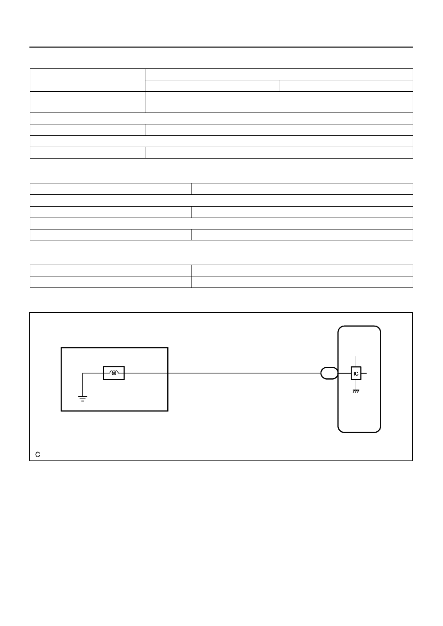
E1
Electronically Controlled
Transmission Solenoid
ECM
10
E7
S2
15
B
W–L
S2
+B
CPU
–
DIAGNOSTICS
AUTOMATIC TRANSMISSION
DI–647
841
TYPICAL ENABLING CONDITIONS
It
Specification
Item
Minimum
Maximum
The monitor will run whenever these
DTCs are not present.
See page
Range check (Low resistance)
Shift solenoid valve S2
ON
Range check (High resistance)
Shift solenoid valve S2
OFF
TYPICAL MALFUNCTION THRESHOLDS
Detection criteria
Threshold
Range check (Low resistance)
Shift solenoid valve S2 resistance
8
Ω
or less
Range check (High resistance)
Shift solenoid valve S2 resistance
100 k
Ω
or more
COMPONENT OPERATING RANGE
Parameter
Standard value
Shift solenoid valve S2
Resistance: 11 to 15
Ω
at 20
°
C (68
°
F)
WIRING DIAGRAM