Toyota Sequoia (2005). Manual - part 136


  Главная      Automobile - Toyota     Toyota Sequoia - Repair manual 2005 year


поиск по сайту           правообладателям


содержание   ..  134  135  136  137   ..


Toyota Sequoia (2005). Manual - part 136


A23451

B17516

Air

A

B17517

Air

A

DIAGNOSTICS

ENGINE

DI–339

533

10

Check air injection pipe between air switching valve No.2 and exhaust manifold.

CHECK:
(a)

Check that the air injection pipe between the air switching
valve(s) No.2 and exhaust manifold is securely con-
nected.

OK:

The air injection pipe is securely connected.

CHECK:
(a)

Check the air injection pipe for blockages and damage.

OK:

The air injection pipe have no blockages and damage.

NG

Repair or replace air injection pipe.

OK

Check for intermittent problems
 (See page 

DI–11

).

11

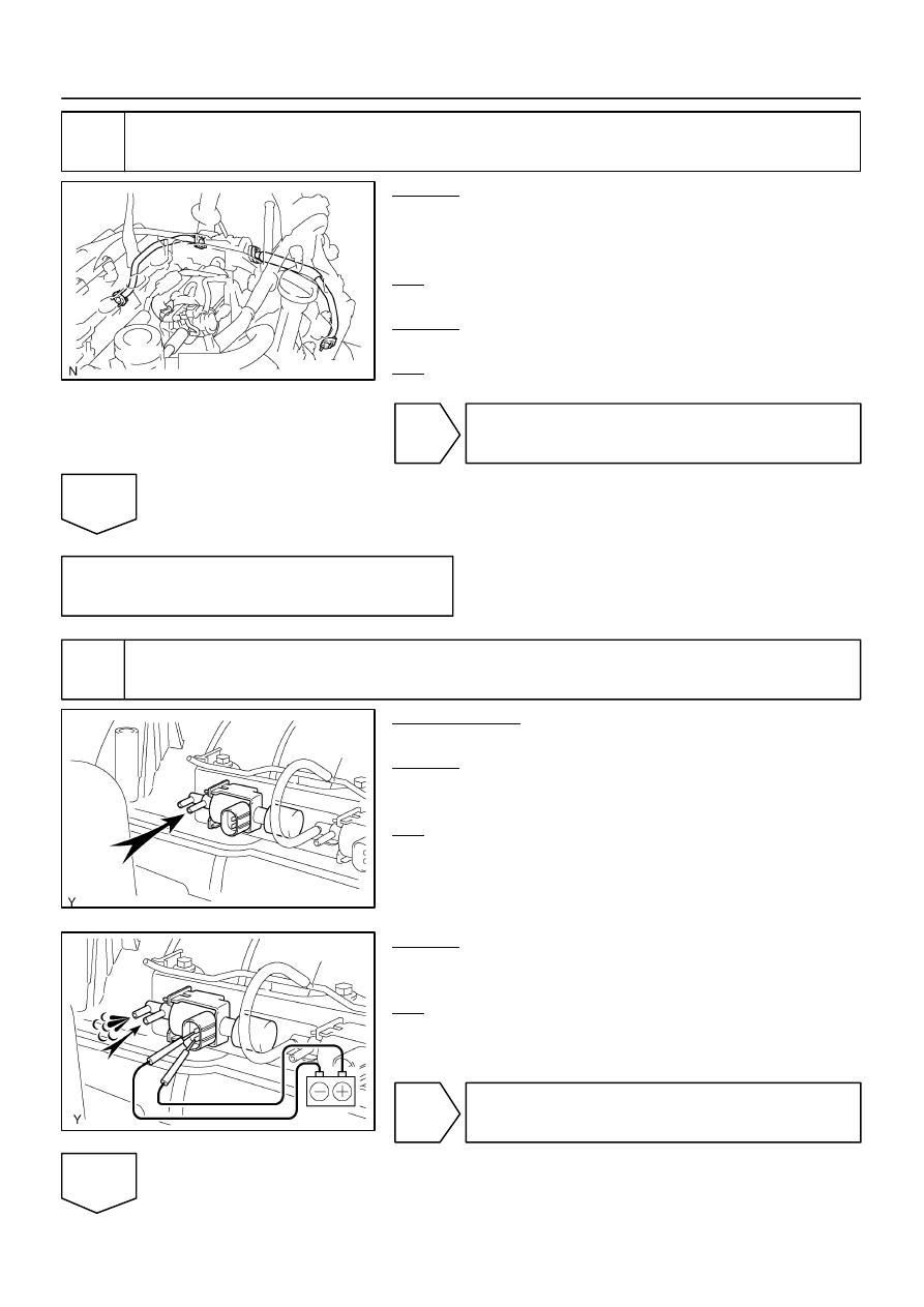
Check VSV for air injection control.

PREPARATION:
Disconnect the 2 vacuum hoses.
CHECK:
Check that air does not flow from the port A as shown in the il-
lustration.
OK:

Not flow from port A

CHECK:
Apply battery positive across the terminals, check that air flows
from the port A.
OK:

Flow from port A

NG

Replace VSV for air injection control.

OK

B17412

E8

AIV1

AIV2

B17437

V14

VSV Connector

V15

Wire Harness Side:

DI–340

DIAGNOSTICS

ENGINE

534

12

Check for open and short circuit in harness and connector between ECM and
VSV for air injection system control

PREPARATION:
(a)

Remove the intake manifold (see page 

EM–36

).

(b)

Disconnect the E8 ECM connector.

(c)

Disconnect the VSV for air injection system control con-
nector.

CHECK:
Measure the resistance between the VSV connector and ECM.
OK:

Standard:

Tester connection

Specified condition

E8–27 (AIV1) – V14–2

Below 1  

E8–26 (AIV1) – V15–2

Below 1  

CHECK:
Measure the resistance between the VSV connector and body
ground.
OK:

Standard:

Tester connection

Specified condition

E8–27 (AIV1) or V14–2 and Body

ground

10 K

 or higher

E8–26 (AIV1) or V15–2 and Body

ground

10 K

 or higher

NG

Repair or replace harness or connector.

OK

B17444

Wire Harness Side:

Air Injection Driver Connector

A41

VV

B17440

A46

Air Switching Valve Connector

Wire Harness Side:

B17440

A46

Air Switching Valve Connector

Wire Harness Side:

DIAGNOSTICS

ENGINE

DI–341

535

13

Check for open and short in harness and connector between air injection driver
and air switching valve.

PREPARATION:
(a)

Remove the intake manifold (see page 

EM–36

).

(b)

Disconnect the A41 air injection driver connector.

(c)

Disconnect the A46 air switching valve connector.

CHECK:
Measure the resistance between the wire harness side connec-
tors.
OK:

Standard:

Tester Connection

Specified Condition

VV (A41–6) – A46–1

Below 1 

VV (A41–6) or A46–1 – 

Body ground

10 k

 or higher

NG

Repair or replace harness or connector and go
to step 6.

OK

14

Check for open in harness and connector between air switching valve and body
ground.

PREPARATION:
(a)

Remove the intake manifold (see page 

EM–36

).

(b)

Disconnect the A46 air switching valve connector.

CHECK:
Measure the resistance between the wire harness side connec-
tors and body ground.
OK:

Standard:

Tester Connection

Specified Condition

A46–2 – Body ground

Below 1 

NG

Repair or replace harness or connector and go
to step 6.

OK

B17444

Wire Harness Side:

Air Injection Driver Connector

A41

SIV

B17417

E4

AIRV

DI–342

DIAGNOSTICS

ENGINE

536

15

Check for open and short in harness and connector between air injection driver
and ECM.

PREPARATION:
(a)

Disconnect the air injection driver connector.

(b)

Disconnect the E4 ECM connector.

CHECK:
Measure the resistance between the wire harness side connec-
tors.
OK:

Standard:

Tester Connection

Specified Condition

SIV (A41–3) – AIRV (E4–4)

Below 1 

SIV (A41–3) or AIRV (E4–4)  – 

Body ground

10 k

 or higher

NG

Repair or replace harness or connector and go
to step 6.

OK

Replace ECM (See page 

SF–80

).


содержание   ..  134  135  136  137   ..