содержание .. 118 119 120 121 ..
Toyota Sequoia (2005). Manual - part 120
A23486
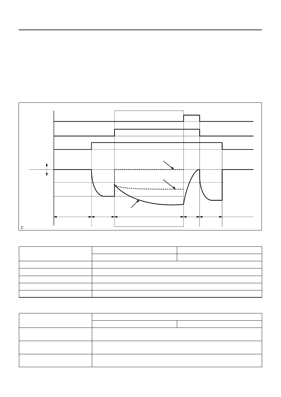
Purge VSV
Vent Valve
Vacuum Pump
EVAP Pressure
Positive
Leak Pressure
sec
Negative
ON
ON
Sequence
Time
A
10
sec
60
Within 15 minutes
sec
ON
First 0.02 inch
B
C
D
P0455
ON: Open
OFF: Closed
OFF: Vent
ON: Closed
10
Standard
sec
60
E
P0456
OK
EVAP Pressure when EVAP system Leaks:
Leak Pressure
Second 0.02 inch
Standard x 0.2
–
DIAGNOSTICS
ENGINE
DI–275
469
(a)
P0455: EVAP (Evaporative Emission) gross leak
In operation C, the vacuum pump creates negative pressure (vacuum) in the EVAP system and the EVAP
system pressure is measured. If the stabilized system pressure is higher than [second 0.02 inch leak pres-
sure standard x 0.2] (near atmospheric pressure), the ECM determines that the EVAP system has a large
leakage, illuminates the MIL and sets the DTC (2 trip detection logic).
(b)
P0456: EVAP very small leak
In operation C, the vacuum pump creates negative pressure (vacuum) in the EVAP system and the EVAP
system pressure is measured. If the stabilized system pressure is higher than second 0.02 inch leak pres-
sure standard, the ECM determines that the EVAP system has a small leakage, illuminates the MIL and sets
the DTC (2 trip detection logic).
MONITOR STRATEGY
R l t d DTC
P0455
Gross leak detected
Related DTCs
P0456
Very small leak (0.020 inch hole) detected
Required sensors/components
Purge VSV, Pump module
Frequency of operation
Once per driving cycles
Duration
Within 15 min. (varies with amount of fuel in tank)
MIL operation
2 driving cycles
Sequence of operation
None
TYPICAL ENABLING CONDITIONS
It
Specification
Item
Minimum
Maximum
The monitor will run whenever these
DTCs are not present
See page
Following values are when atmospheric is
760 mmHg (100 kPa)
–
EVAP key–off monitor runs when all of the
following conditions met:
–