Toyota Sequoia (2005). Manual - part 1021


  Главная      Automobile - Toyota     Toyota Sequoia - Repair manual 2005 year


поиск по сайту           правообладателям


содержание   ..  1019  1020  1021 


Toyota Sequoia (2005). Manual - part 1021


294

SEQUOIA (EM00Z0U)

Air Conditioning

B

8

B

20

B

13

B

16

B

11

B

10

B

9

B

12

B

15

B

22

D

4

D

2

D

5

2

1

B

2

B

4

A1

3

TE

SG–TE

ACT

TW

AC1

S5–AM

TP

SG–TP

AMC

AMH

S5–AI

TP1

SG–TPI

AIR

AIF

E 5

G–

B

W–G

LG–

B

W–R

G–

B

R–

Y

G–

R

L–

R

W–L

R–

L

L–

B

W

Y–

R

G–

W

R

G–B

ACT

THWO

AC1

D

1

2LO

P–

L

LMS

O

O(

1)

O

O(

1)

VZ

PT

GND

REC

FRS

M

MCOOL

MHOT

GND

PT

VZ

M

5

3

4

2

1

1

3

2

4

5

A17

A16

I19(A), I20(B), I21(C), I22(D)

24

14

25

9

TACH

1

Y–

G

A

D

A

D

J14(A)

Y–G

Y–

G

A

/C

 E

vapor

ator

 Tem

p

S

ensor

 (

Fr

ont

)

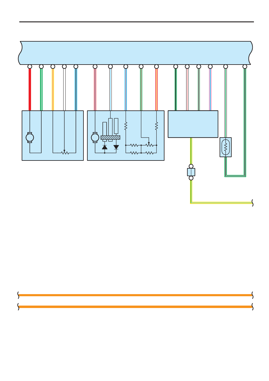
Air Inlet Control Servo Motor

Air Mix Control Servo Motor (Front)

Engine Control Module

Integration Control and Panel

Junction
Connector

SEQUOIA (EM00Z0U)

295

IF2

9

IF1

8

10

12

IF1

B A

IF2

12

2

B

14

B

21

2

1

D

13

D

14

A3

1

SGRrTR

RrTR

S5–TR

TS

R–

Y

GR

R

J3

1

(A

), J

3

2

(B

)

B

LG

I19(A), I20(B), I21(C), I22(D)

B

GR

R

R–

Y

IG

O

A

10

GND

O

C

14

IF2

11

C

4

C

15

IF1

C

5

C

6

W–B

O

O

6

8

9

4

3

2

RrSWD

RrDPD

RrCLK

RrBLK

RrSTX

W

R

B

LG–

B

G–

Y

G–

Y

LG–

B

B

R

W

A28

STX

BLK

CLK

DPD

SWD

GND

A

E

B

F

B

A

IF2

1

2

B

1

B

3

A1

4

TR

SG–TR

L–

W

R–

W

L–W

11

IF1

13

IF2

10

IF1

4

(

4)

(

3)

IF1

15

IF2

13

(

3)

(

4)

A

A

A

 1 : w/ Rear A/C

J43

 3 : w/ Rear Seat Entertainment System, Rear Seat Audio System

O(

1)

A

A

D

3

IGN

Y–

G

Y–G

O

1

A1

5

(

1

)

(

1

)

(

1

)

(

1

)

(

1

)

(

1

)

(

1

)

(

1

)

(

1

)

(

1

)

(

1

)

(

1

)

(

1

)

(

1

)

 4 : w/o Rear Seat Entertainment System, Rear Seat Audio System

(

1

)

(

1

)

IF1

9

IF2

3

(

3)

(

4)

R–

L

(

1

)

R–L

(

1)

IG

10

A

/C

 R

oom

 Tem

p

.  S

ensor

 (

Fr

ont

)

A/

C So

la

r Se

n

so

r

A/C Control

(Rear Heater Control Panel)

A/

C Ro

o

m

 T

e

m

p

S

ensor

 (

R

ear

)

Integration Control and Panel

Juncti

on C

onnector

Junction
Connector

296

SEQUOIA (EM00Z0U)

Air Conditioning

R

6

1

5

B

1E

24

R

R

16

3C

3A

D

R

5

A

10A
DOME

2C

15

3E

15A
GAUGE

1E

7

A

2

3

D

5 1J

3E

3A

IG+

(

1

)

B

R–

L

8

R–

L

+B

R–L

R–L

R–

L

A

11

PP

15A
CIG

1E

20

P

ACC

J15(B)

I19(A), I20(B), I21(C), I22(D)

32

13

(

1)

A

MPX–

3 A

MPX+

MPX1

MPX2

L–

Y

LG–

B

C 5

B 5

 1 : w/ Rear A/C

Body
ECU

Combination
Meter

Integration Control and Panel

Junction
Connector

(BAT)

(ACC)

(IG)

SEQUOIA (EM00Z0U)

297

The A/C control assembly receives various signals, I.E., the engine RPM from the engine control module, out side air
temperature signal from the A/C ambient temp. sensor and coolant temperature from the engine control module, etc.
When the engine is started and the A/C SW (Integration control and panel) is on, a signal is input to the integration control
and panel.
As a result, current flows from HTR fuse to TERMINAL 2 of the MG CLT relay to TERMINAL 1 to TERMINAL MGC of the
integration control and panel to GROUND, turning the MG CLT relay on, so that the magnetic clutch is on and the A/C
compressor operates.
If the integration control and panel detects the following conditions, it stops the air conditioning:

Evaporator outlet air is too low.

There is a marked difference between the compressor speed and the engine speed.

The refrigerant pressure is abnormally high or abnormally low.

The engine speed is too low.

Rapid acceleration occurs.

  :  Parts Location

Code

See Page

Code

See Page

Code

See Page

A1

40

A31

46

I22

D

43

A2

40

A34

46

J1

41

A3

40

A35

46

J3

41

A4

40

B3

42

J14

A

44

A13

42

B4

42

J15

B

44

A14

42

B5

42

J18

44

A15

42

B15

46

J31

A

44

A16

42

C5

42

J32

B

44

A17

42

E5

43

J43

44

A18

42

F10

22, 40

J48

A

44

A28

42

I19

A

43

J49

B

44

A29

46

I20

B

43

J50

41

A30

46

I21

C

43

J57

46

: Relay Blocks

Code

See Page

Relay Blocks (Relay Block Location)

2

26

Engine Room R/B No.2 (Engine Compartment Left)

4

27

Engine Room R/B No.4 (Engine Compartment Right)

: Junction Block and Wire Harness Connector

Code

See Page

Junction Block and Wire Harness (Connector Location)

1E

33

Cowl Wire and Instrument Panel J/B (Lower Finish Panel)

1J

33

Engine Room Main Wire and Instrument Panel J/B (Lower Finish Panel)

2C

29

Engine Room Main Wire and Engine Room J/B (Engine Compartment Left)

2G

29

Engine Room Main Wire and Engine Room J/B (Engine Compartment Left)

3A

36

Cowl Wire and Sub J/B No.3 (Upper the Accelerator Pedal)

3C

36

Cowl Wire and Sub J/B No.3 (Upper the Accelerator Pedal)

3E

36

Cowl Wire and Sub J/B No.3 (Upper the Accelerator Pedal)

4A

38

Cowl Wire and Sub J/B No.4 (Upper the Accelerator Pedal)

4D

38

Cowl Wire and Sub J/B No.4 (Upper the Accelerator Pedal)

4E

38

Cowl Wire and Sub J/B No.4 (Upper the Accelerator Pedal)

System Outline


содержание   ..  1019  1020  1021