содержание .. 97 98 99 100 ..
Toyota Sequoia (2005). Manual - part 99
A21343
I9
I10
I11
I12
I13
I14
I15
I16
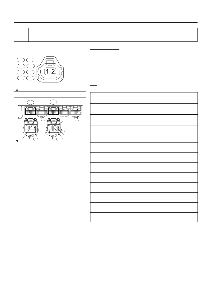
Wire Harness Side:
Injector Connector
B17413
E6
#40
#50
#20
#10
#30
#60
#70
#80
E8
–
DIAGNOSTICS
ENGINE
DI–199
393
10
Check for open and short in harness and connector between ignition SW and in-
jector, injector and ECM of misfiring cylinder.
PREPARATION:
(a)
Disconnect the I9, I10, I11, I12, I13, I14, I15 or I16 injector
connector.
(b)
Disconnect the E6 or E8 ECM connector.
CHECK:
Measure the resistance of the wire harness side connectors be-
tween the ECM and injector.
OK:
Standard:
Tester Connection
Specified Condition
Injector (I9–2) – #10 (E6–2)
Below 1
Ω
Injector (I10–2) – #20 (E6–3)
Below 1
Ω
Injector (I11–2) – #30 (E6–4)
Below 1
Ω
Injector (I12–2) – #40 (E6–5)
Below 1
Ω
Injector (I13–2) – #50 (E6–6)
Below 1
Ω
Injector (I14–2) – #60 (E6–7)
Below 1
Ω
Injector (I15–2) – #70 (E8–3)
Below 1
Ω
Injector (I16–2) – #80 (E8–2)
Below 1
Ω
Injector (I9–2) or #10 (E6–2) –
Body ground
10 k
Ω
or higher
Injector (I10–2) or #20 (E6–3) –
Body ground
10 k
Ω
or higher
Injector (I11–2) or #30 (E6–4) –
Body ground
10 k
Ω
or higher
Injector (I12–2) or #40 (E6–5) –
Body ground
10 k
Ω
or higher
Injector (I13–2) or #50 (E6–6) –
Body ground
10 k
Ω
or higher
Injector (I14–2) or #60 (E6–7) –
Body ground
10 k
Ω
or higher
Injector (I15–2) or #70 (E8–3) –
Body ground
10 k
Ω
or higher
Injector (I16–2) or #80 (E8–2) –
Body ground
10 k
Ω
or higher