Toyota Sequoia (2005). Manual - part 83


  Главная      Automobile - Toyota     Toyota Sequoia - Repair manual 2005 year


поиск по сайту           правообладателям


содержание   ..  81  82  83  84   ..


Toyota Sequoia (2005). Manual - part 83


B17411

E2

VC

E8

ECM Connector

DIAGNOSTICS

ENGINE

DI–135

329

3

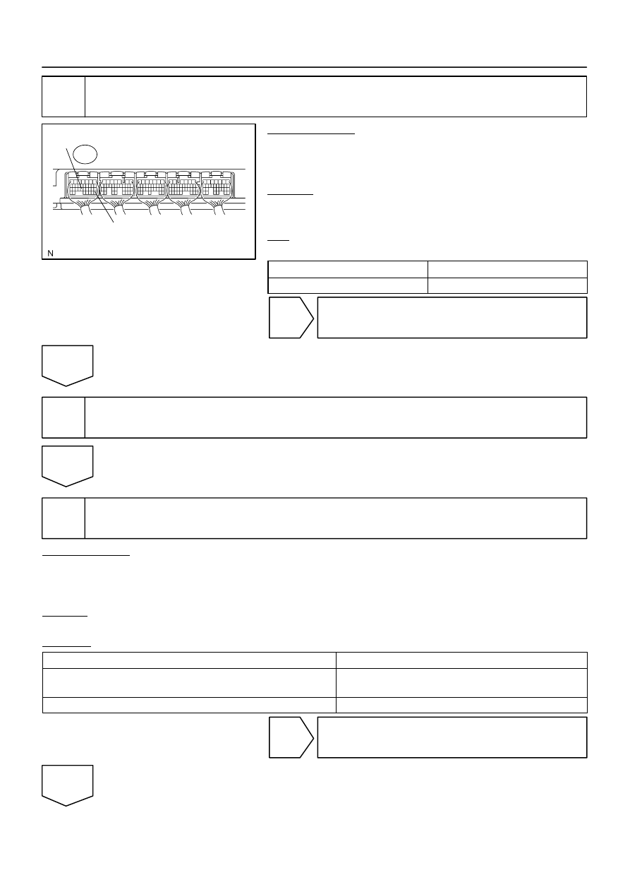
Check voltage between terminals VC and E2 of ECM connector.

PREPARATION:
(a)

Disconnect the T14 throttle control motor and sensor con-
nector.

(b)

Turn the ignition switch ON.

CHECK:
Measure the voltage between the specified terminals of the E8
ECM connector.
OK:

Standard:

Tester Connection

Specified Condition

VC (E8–23) – E2 (E8–28)

4.5 to 5.5 V

NG

Replace ECM (See page 

SF–80

).

OK

4

Replace throttle body (See page 

SF–42

).

Go

5

Check if DTC output recur.

PREPARATION:
(a)

Clear the DTC (See page 

DI–43

).

(b)

Start the engine.

(c)

Run the engine at idle for 15 seconds or more.

CHECK:
Read the DTC.
RESULT:

Display (DTC Output)

Proceed to

”P0120, P0122, P0123, P0220, P0222, P0223 and/or P2135” are output

again

A

No DTC output

B

B

System is OK.

A

DI–136

DIAGNOSTICS

ENGINE

330

Replace ECM (See page 

SF–80

).

DIAGNOSTICS

ENGINE

DI–137

331

DTC

P0121

Throttle/Pedal Position Sensor/Switch ”A”
Circuit Range/Performance Problem

HINT:
This is the purpose of the ”throttle position sensor”.

CIRCUIT DESCRIPTION

Refer to DTC P0120 on page 

DI–127

.

DTC No.

DTC Detecting Condition

Trouble Area

P0121

Condition (a) continues for 2.0 sec.:

(a) Difference between VTA1 and VTA2 deviates from the

threshold

Throttle control motor and sensor

MONITOR DESCRIPTION

The ECM uses throttle position sensor to monitor the throttle valve opening angle.
This sensor includes two signals, VTA1 and VTA2. VTA1 is used to detect the throttle opening angle and
VTA2 is used to detect malfunctions in VTA1. There are several checks that the ECM performs confirm prop-
er operation of the throttle position sensor and VTA1. 
There is a specific voltage difference expected between VTA1 and VTA2 for each throttle opening angle.
If the voltage output difference of the VTA1 and VTA2 deviates from the normal operating range, the ECM
interprets this as a malfunction of the throttle position sensor. The ECM will turn on the MIL and a DTC is
set.

FAIL SAFE

If the ETCS (Electronic Throttle Control System) has a malfunction, the ECM cuts off current to the throttle
control motor. The throttle control valve returns to a predetermined opening angle (approximately 16

°

) by

the force of the return spring. The ECM then adjusts the engine output by controlling the fuel infection (inter-
mittent fuel–cut) and ignition timing in accordance with the accelerator pedal opening angle to enable the
vehicle to continue at a minimum speed.
If the accelerator pedal is depressed firmly and slowly, the vehicle can be driven slowly.
If a ”pass” condition is detected and then the ignition switch is turned OFF, the fail–safe operation will stop
and the system will return to normal condition.

MONITOR STRATEGY

Related DTCs

P0121

Throttle position sensor rationality

Required sensors/components

Throttle position sensor

Frequency of operation

Continuous

Duration

2 sec.

MIL operation

Immediate

Sequence of operation

None

TYPICAL ENABLING CONDITIONS

It

Specification

Item

Minimum

Maximum

The monitor will run whenever this DTC is
not present

See page 

DI–18

VTA2 voltage

4.6 V

DI3HR–14

DI–138

DIAGNOSTICS

ENGINE

332

TYPICAL MALFUNCTION THRESHOLDS

Detection Criteria

Threshold

Different between VTA1 and VTA2 
|VTA1 – (VTA2 

×

 0.8 to 1.2)|*

* Corrected by learning value

Less than 0.8 V and more than 1.6 V

INSPECTION PROCEDURE

HINT:
Read freeze frame data using 

the hand−held tester

. Freeze frame data records the engine conditions when

a malfunction is detected. When troubleshooting, freeze frame data can help determine if the vehicle was
running or stopped, if the engine was warmed up or not, if the air–fuel ratio was lean or rich, as well as other
data from the time when a malfunction occurred.

Replace throttle control motor and sensor (See page 

SF–42

).


содержание   ..  81  82  83  84   ..