содержание .. 78 79 80 81 ..
Toyota Sequoia (2005). Manual - part 80
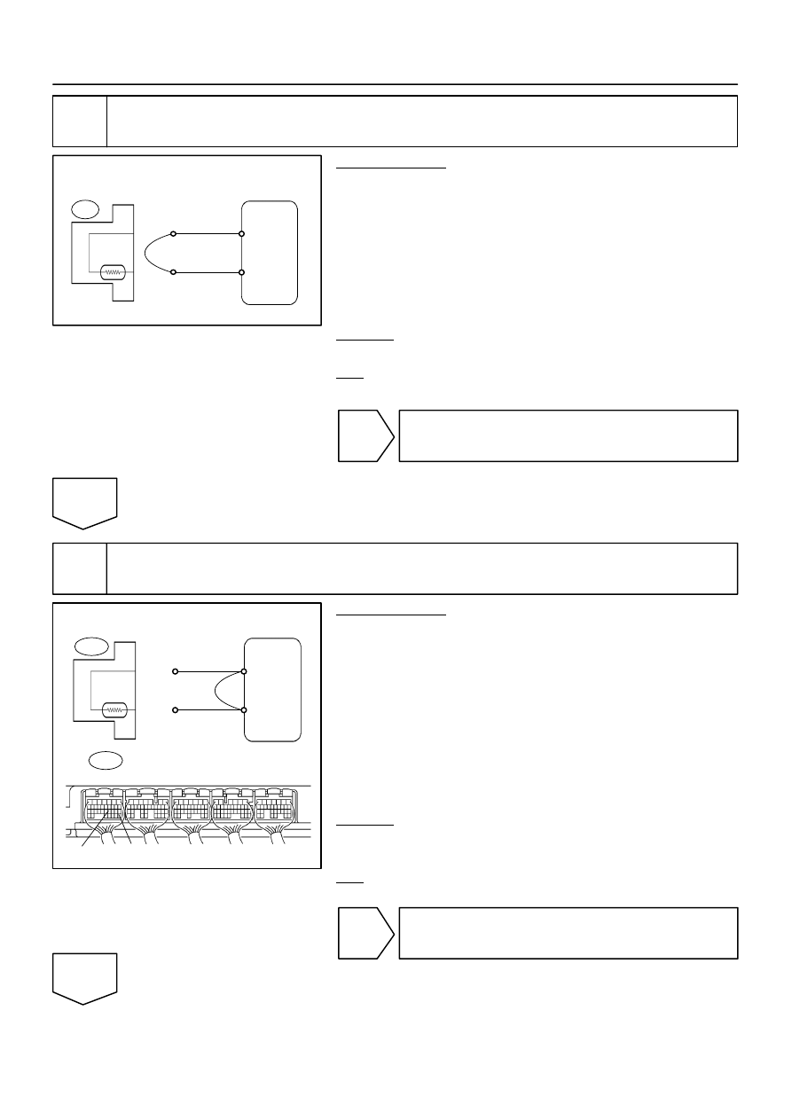
A19552
Engine Coolant
Temp. Sensor
2
1
THW
E2
ECM
E2
B17441
Engine Coolant
Temp. Sensor
ECM
E2
THW
E2
THW
E2
E8
ECM Connector
–
DIAGNOSTICS
ENGINE
DI–123
317
2
Check for open in harness or ECM.
PREPARATION:
(a)
Disconnect the E2 engine coolant temperature (ECT)
sensor connector.
(b)
Connect terminals 1 and 2 of the engine coolant tempera-
ture sensor wire harness side connector.
(c)
Turn the ignition switch ON.
(d)
When using hand–held tester, enter the following menu:
DIAGNOSIS / ENHANCED OBD II / DATA LIST / ALL /
COOLANT TEMP.
CHECK:
Read the temperature value on the hand–held tester.
OK:
Standard: Temperature value: 140
°
C (284
°
F) or more
OK
Confirm good connection at sensor. If OK, re-
place engine coolant temperature sensor.
NG
3
Check for open in harness or ECM.
PREPARATION:
(a)
Disconnect the E2 engine coolant temperature sensor
connector.
(b)
Connect terminals THW and E2 of the E8 ECM connector.
HINT:
Before checking, do a visual and contact pressure checks for
the ECM connector.
(c)
Turn the ignition switch ON.
(d)
When using hand–held tester, enter the following menu:
DIAGNOSIS / ENHANCED OBD II / DATA LIST / ALL /
COOLANT TEMP.
CHECK:
Read the temperature value on the OBD II scan tool or the
hand–held tester.
OK:
Standard: Temperature value: 140
°
C (284
°
F) or more
OK
Repair or replace harness or connector.
NG