содержание .. 72 73 74 75 ..
Toyota Sequoia (2005). Manual - part 74
A21341
+B
OX
E1
HT
H2
H4
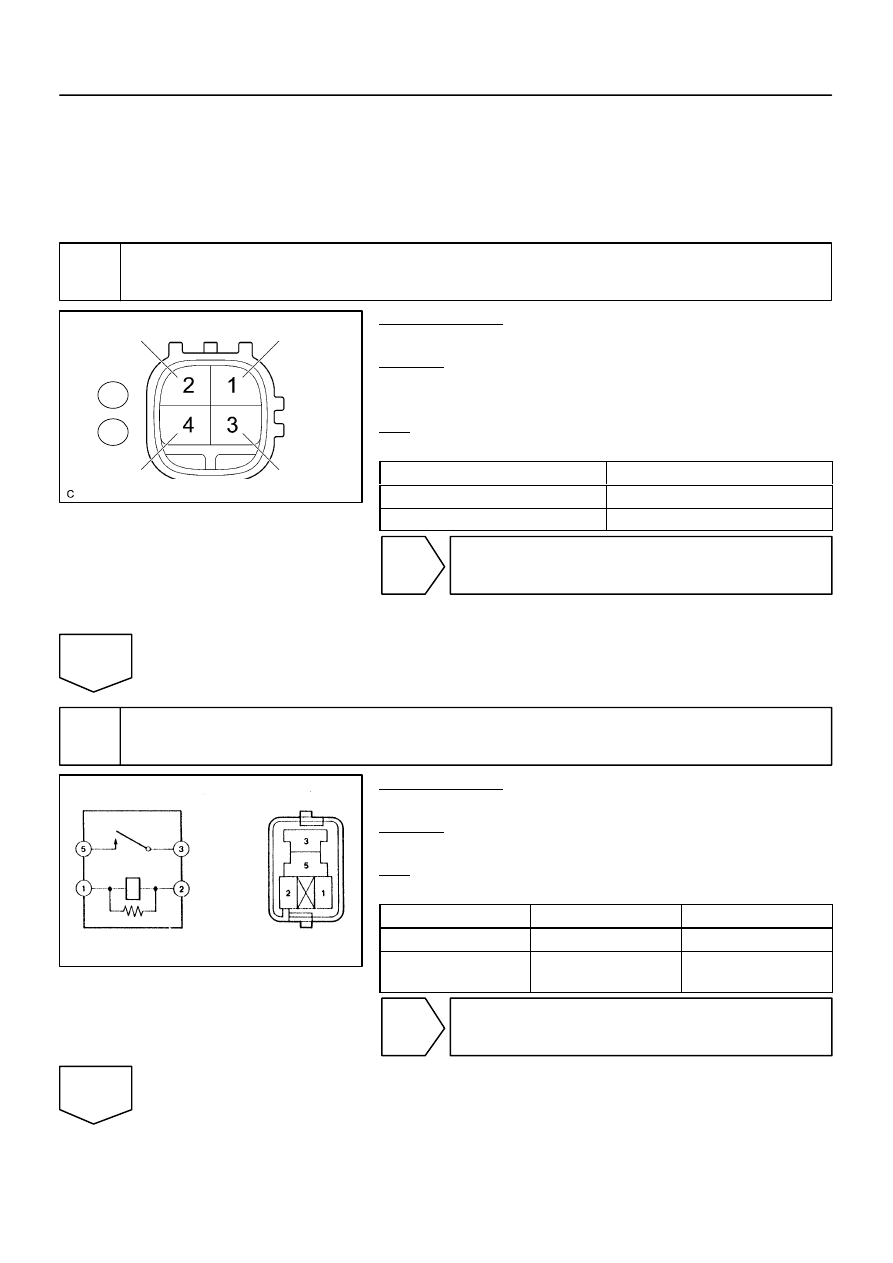
Components Side:
Bank 1 Sensor 2, Bank 2 Sensor 2
A19288
EFI Relay
–
DIAGNOSTICS
ENGINE
DI–99
293
INSPECTION PROCEDURE
HINT:
Read freeze frame data using hand–held tester. Because freeze frame records the engine conditions when
the malfunction is detected. When troubleshooting, it is useful to determine whether the vehicle was running
or stopped, the engine was warmed up or not, the air–fuel ratio was lean or rich, etc. when a malfunction
occurred.
1
Check resistance of heated oxygen sensor heater.
PREPARATION:
Disconnect the H2 or H4 heated oxygen sensor connector.
CHECK:
Measure resistance between terminals of the heated oxygen
sensor.
OK:
Standard:
Tester Connection
Specified Condition
HTL2 (H2–1) – +B (H2–2)
11 to 16
Ω
(20
°
C)
HTR2 (H4–1) – +B (H4–2)
11 to 16
Ω
(20
°
C)
NG
Replace heated oxygen sensor.
OK
2
Check EFI relay.
PREPARATION:
Remove the EFI relay from the engine room J/B.
CHECK:
Inspect the EFI relay.
OK:
Standard:
Terminal No.
Condition
Specified Condition
3 – 5
Always
10 K
Ω
or higher
3 – 5
Apply B+ between
terminals 1 and 2
Below 1
Ω
NG
Replace EFI relay.
OK