содержание .. 57 58 59 60 ..
Toyota Sequoia (2005). Manual - part 59
A23656
0.2 V/DIV
200 msec./DIV
Ground
A23657
10 msec./DIV
5 V/DIV
Ground
–
DIAGNOSTICS
ENGINE
DI–39
233
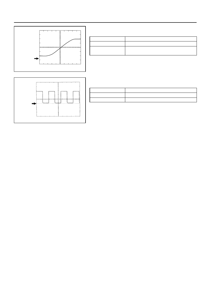
WAVEFORM 10
Heated oxygen sensor
ECM Terminal Names
Between OX1B and E2
Tester Ranges
0.2 V/DIV, 200 msec./DIV
Conditions
Engine speed maintained 2,500 rpm for 2 minutes after
warming up sensor
HINT:
In the DATA LIST, item O2S B1S2 shows the ECM input values
from the heated oxygen sensor.
WAVEFORM 11
Engine speed signal
ECM Terminal Names
Between TACH and E1
Tester Ranges
5 V/DIV, 10 msec./DIV
Conditions
Idling
HINT:
The wavelength becomes shorter as vehicle speed increases.