содержание .. 53 54 55 56 ..
Toyota Sequoia (2005). Manual - part 55
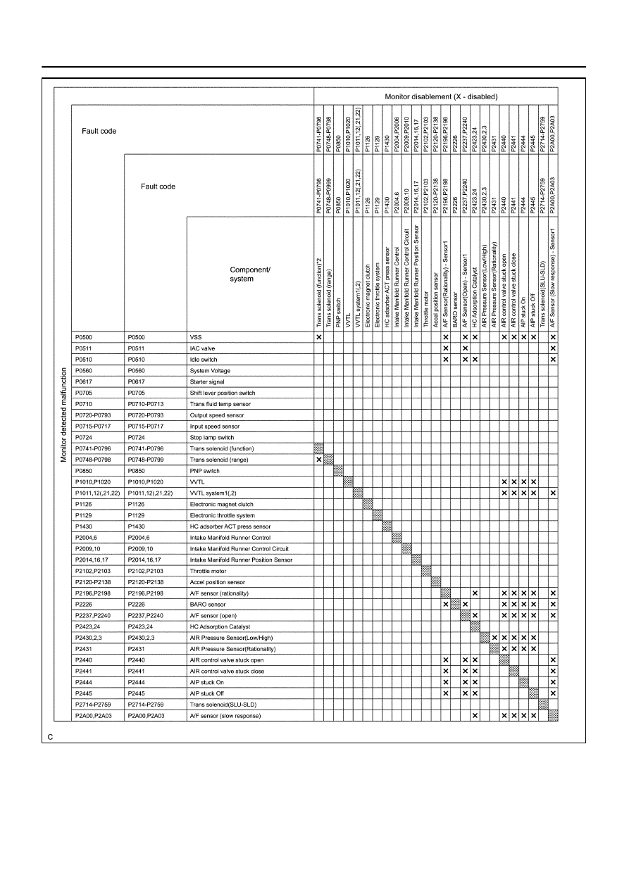
A21576
–
DIAGNOSTICS
ENGINE
DI–23
217
Главная Automobile - Toyota Toyota Sequoia - Repair manual 2005 year
поиск по сайту правообладателям
|
|
|
содержание .. 53 54 55 56 ..
A21576 – DIAGNOSTICS ENGINE DI–23 217 |