Content .. 2704 2705 2706 2707 ..
Toyota Tundra (2015 year). Manual - part 2706
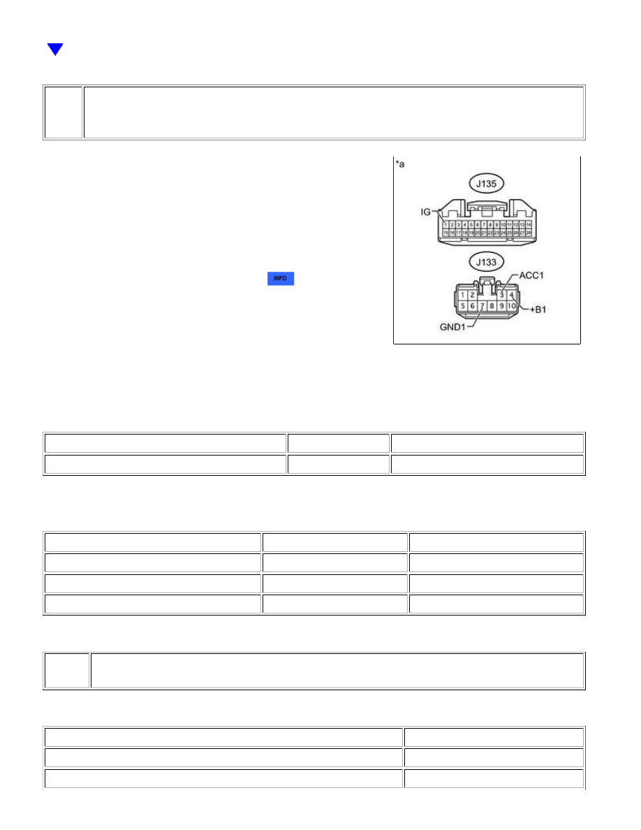
4.
CHECK HARNESS AND CONNECTOR (NAVIGATION RECEIVER ASSEMBLY - BATTERY
AND BODY GROUND)
(a) Connect the cable to the negative (-) battery terminal.
NOTICE:
When disconnecting the cable, some systems need to be
initialized after the cable is reconnected
.
(b) Disconnect the J133 navigation receiver assembly connector.
(c) Measure the resistance according to the value(s) in the table below.
Standard Resistance:
TESTER CONNECTION
CONDITION
SPECIFIED CONDITION
J133-7 (GND1) - Body ground
Always
Below 1 Ω
(d) Measure the voltage according to the value(s) in the table below.
Standard Voltage:
TESTER CONNECTION
CONDITION
SPECIFIED CONDITION
J133-4 (+B1) - Body ground
Always
11 to 14 V
J133-3 (ACC1) - Body ground
Ignition switch ACC
11 to 14 V
J135-1 (IG) - Body ground
Ignition switch ON
11 to 14 V
Text in Illustration
*a
Result
RESULT
PROCEED TO
OK (for Column Shift Type)
A
OK (for Floor Shift Type)
B
CAN COMMUNICATION: CAN COMMUNICATION SYSTEM: Naviga...