Content .. 1898 1899 1900 1901 ..
Toyota Tundra (2015 year). Manual - part 1900
OK
OK
(b) Disconnect the D74 ECM connector.
(c) Measure the resistance according to the value(s) in the table below.
Standard resistance:
TESTER CONNECTION
CONDITION
SPECIFIED CONDITION
D9-5 (VC) - D74-80 (VCTA)
Always
Below 1 Ω
D9-6 (VTA) - D74-78 (VTA1)
Always
Below 1 Ω
D9-4 (VTA2) - D74-77 (VTA2)
Always
Below 1 Ω
D9-3 (E2) - D74-79 (ETA)
Always
Below 1 Ω
D9-5 (VC) or D74-80 (VCTA) - Body ground
Always
10 kΩ or higher
D9-6 (VTA) or D74-78 (VTA1) - Body ground
Always
10 kΩ or higher
D9-4 (VTA2) or D74-77 (VTA2) - Body ground
Always
10 kΩ or higher
NG
REPAIR OR REPLACE HARNESS OR CONNECTOR
3.
INSPECT ECM (VC VOLTAGE)
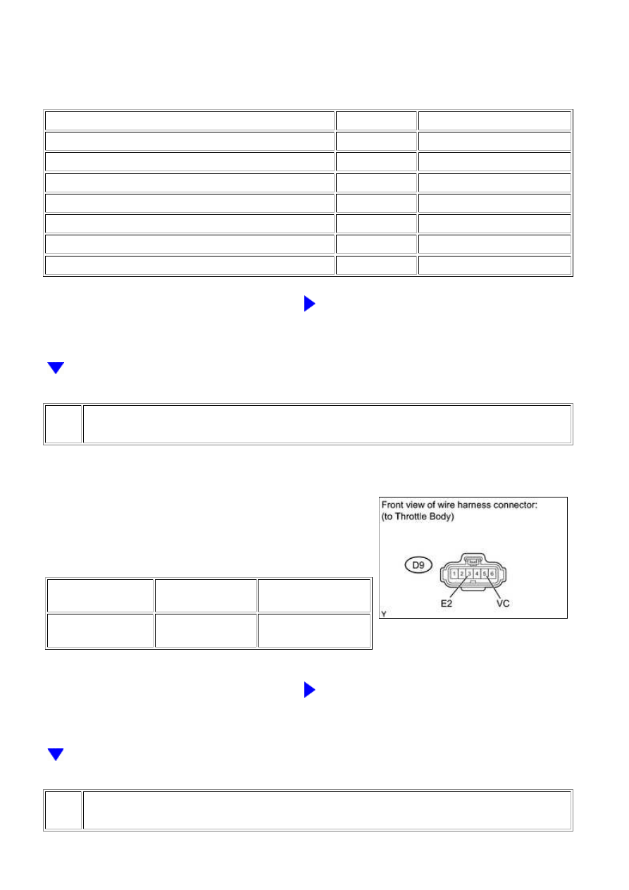
(a) Disconnect the D9 throttle body connector.
(b) Turn the ignition switch to ON.
(c) Measure the voltage according to the value(s) in the
table below.
Standard voltage:
TESTER
CONNECTION
SWITCH
CONDITION
SPECIFIED
CONDITION
D9-5 (VC) - D9-3
(E2)
Ignition switch ON
4.5 to 5.5 V
NG
REPLACE ECM
4.
REPLACE THROTTLE BODY ASSEMBLY
3UR-FE ENGINE CONTROL SYSTEM: SFI SYSTEM: P0120-P0123...