Toyota Tundra (2015 year). Manual - part 1554


  Index      Toyota     Toyota Tundra (2015 year) - Service and Repair Manual


Search            copyright infringement  


Content   ..  1552  1553  1554  1555   ..


Toyota Tundra (2015 year). Manual - part 1554
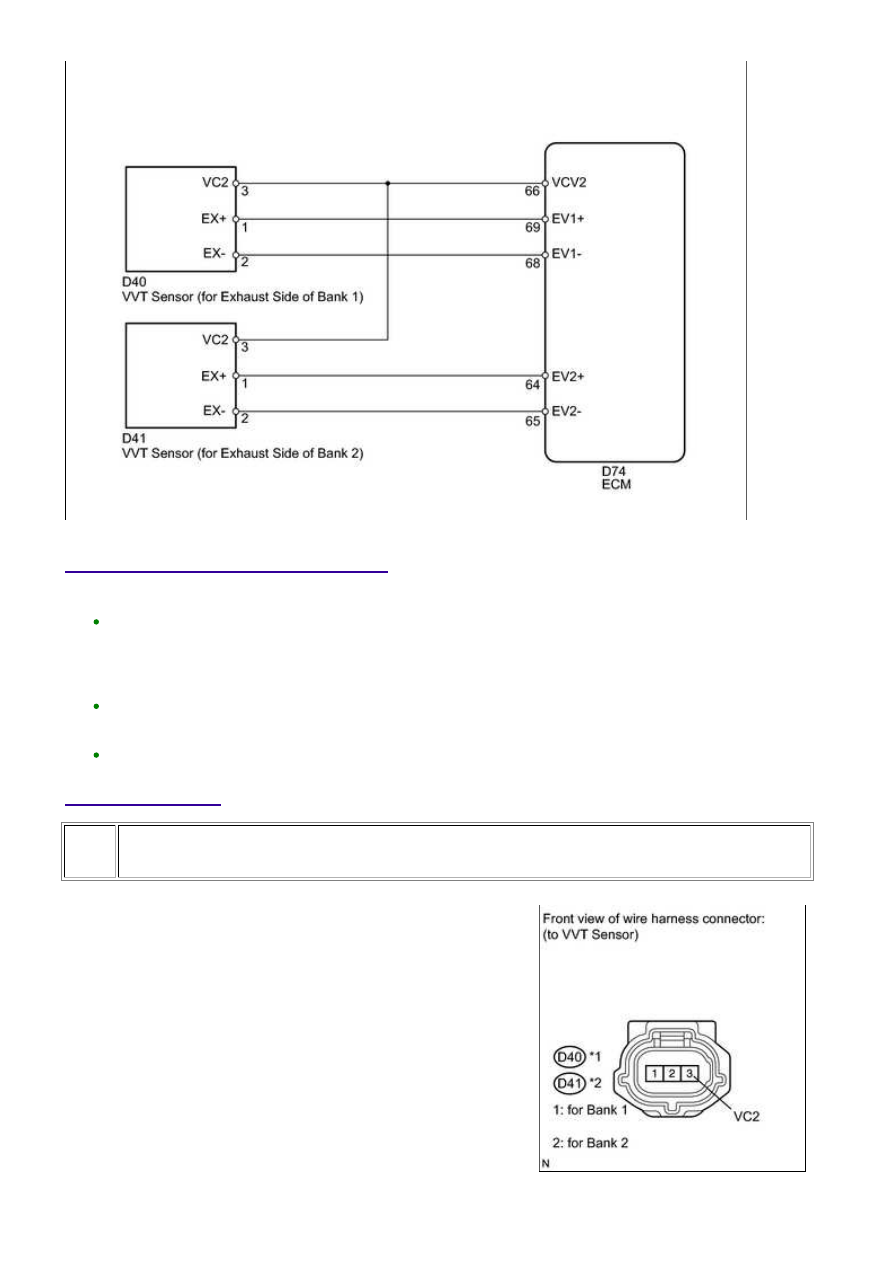


INSPECTION PROCEDURE

HINT:

Bank 2 refers to the bank that does not include the No. 1 cylinder.

PROCEDURE

1.

CHECK HARNESS AND CONNECTOR (SENSOR POWER SOURCE)

(a) Disconnect the D40 or D41 VVT sensor (for exhaust side)

connector.

3UR-FBE ENGINE CONTROL SYSTEM: SFI SYSTEM: P0365,P036...

OK

OK

(b) Measure the voltage according to the value(s) in the table below.

Standard voltage:

TESTER CONNECTION

SWITCH CONDITION

SPECIFIED CONDITION

D40-3 (VC2) - Body ground

Ignition switch ON

4.5 to 5.0 V

D41-3 (VC2) - Body ground

Ignition switch ON

4.5 to 5.0 V

NG

REPAIR OR REPLACE HARNESS OR CONNECTOR

2.

CHECK HARNESS AND CONNECTOR (VVT SENSOR (FOR EXHAUST SIDE) - ECM)

(a) Disconnect the D40 or D41 VVT sensor (for exhaust side) connector.

(b) Disconnect the D74 ECM connector.

(c) Measure the resistance according to the value(s) in the table below.

Standard resistance:

TESTER CONNECTION

CONDITION

SPECIFIED CONDITION

D40-1 (EX+) - D74-69 (EV1+)

Always

Below 1 Ω

D40-2 (EX-) - D74-68 (EV1-)

Always

Below 1 Ω

D41-1 (EX+) - D74-64 (EV2+)

Always

Below 1 Ω

D41-2 (EX-) - D74-65 (EV2-)

Always

Below 1 Ω

D40-1 (EX+) or D74-69 (EV1+) - Body ground

Always

10 kΩ or higher

D40-2 (EX-) or D74-68 (EV1-) - Body ground

Always

10 kΩ or higher

D41-1 (EX+) or D74-64 (EV2+) - Body ground

Always

10 kΩ or higher

D41-2 (EX-) or D74-65 (EV2-) - Body ground

Always

10 kΩ or higher

NG

REPAIR OR REPLACE HARNESS OR CONNECTOR

3.

CHECK SENSOR INSTALLATION (VVT SENSOR (FOR EXHAUST SIDE))

3UR-FBE ENGINE CONTROL SYSTEM: SFI SYSTEM: P0365,P036...

OK

OK

OK

NEXT

(a) Check the VVT sensor (for exhaust side) installation.

OK:

Sensor is installed correctly.

NG

SECURELY REINSTALL SENSOR

4.

CHECK EXHAUST CAMSHAFT

Teeth do not have any cracks or deformation.

NG

REPLACE EXHAUST CAMSHAFT

5.

CHECK VALVE TIMING (CHECK FOR LOOSE TIMING CHAIN AND) 

NG

CHECK ENGINE MECHANICAL SYSTEM

6.

REPLACE VVT SENSOR (FOR EXHAUST SIDE)

(a) Replace the VVT sensor (for exhaust side) 


.

3UR-FBE ENGINE CONTROL SYSTEM: SFI SYSTEM: P0365,P036...

7.

CHECK WHETHER DTC OUTPUT RECURS

(a) Connect the Techstream to the DLC3.

(b) Turn the ignition switch to ON.

(c) Turn the Techstream on.

(d) Clear DTCs 


.

(e) Start the engine.

(f) Drive the vehicle in accordance with the driving pattern described in the Confirmation Driving

Pattern.

(g) Enter the following menus: Powertrain / Engine and ECT / Trouble Codes.

(h) Read DTCs.

Result

DISPLAY (DTC OUTPUT)

PROCEED TO

No output

A

P0365, P0367, P0368, P0390, P0392 or P0393

B

HINT:

If the engine does not start, replace the ECM.

B

REPLACE ECM

A

END

3UR-FBE ENGINE CONTROL SYSTEM: SFI SYSTEM: P0365,P036...


Content   ..  1552  1553  1554  1555   ..